Review: Getting Started with the Yahboom Transbot
Use Foxglove with the robot kit to start understanding your first robot
Robot kits are a great way to learn the basics of robotics development, because you can leverage pre-built platforms to focus on the field’s most exciting problems. There are several companies that curate, assemble, and provide these kits. Yahboom, for example, sells a range of educational robot kits for everyone from the casual hobbyist to professional researcher. After recently trying out their Transbot platform, I can say that I’m a big fan. Based on how easy it was to get up and running, I would recommend it to anyone interested in ditching the textbooks and getting their hands dirty with some hands-on development.
Assembling the Transbot
I ordered the Transbot kit with a Jetson NANO, HD camera, and Depth (LIDAR) camera. My Transbot and its accompanying sensors and accessories arrived in a conveniently insulated carrying case, along with a microSD card pre-installed with ROS.
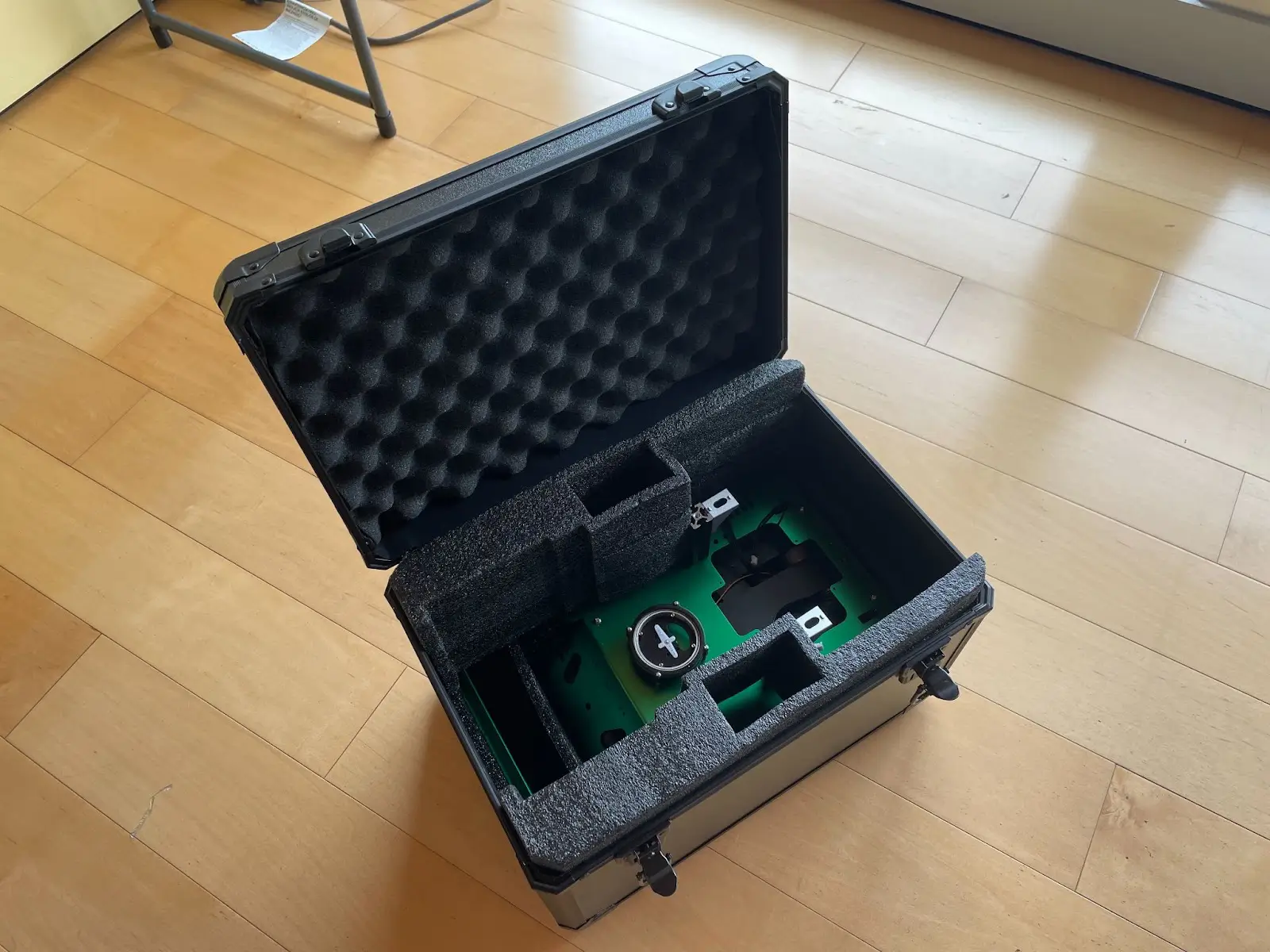
Here I’ve taken out all the accessories to reveal the securely packed Transbot at the bottom of the shipped case.
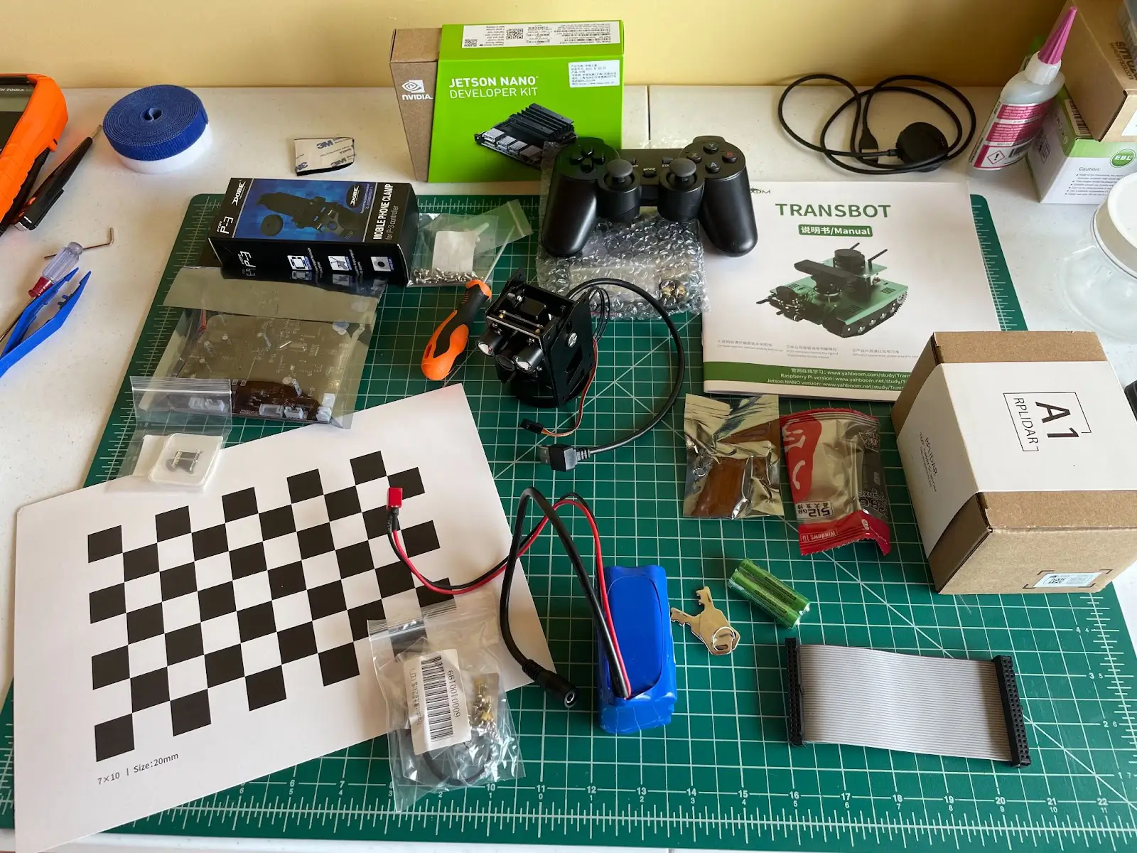
First, I unpacked all the various accessories – a wireless controller with alkaline batteries included, a camera calibration card, the Jetson NANO, and more. The kit also includes a rechargeable battery for the bot, as well as an expansion board with all the motor and servo controllers.
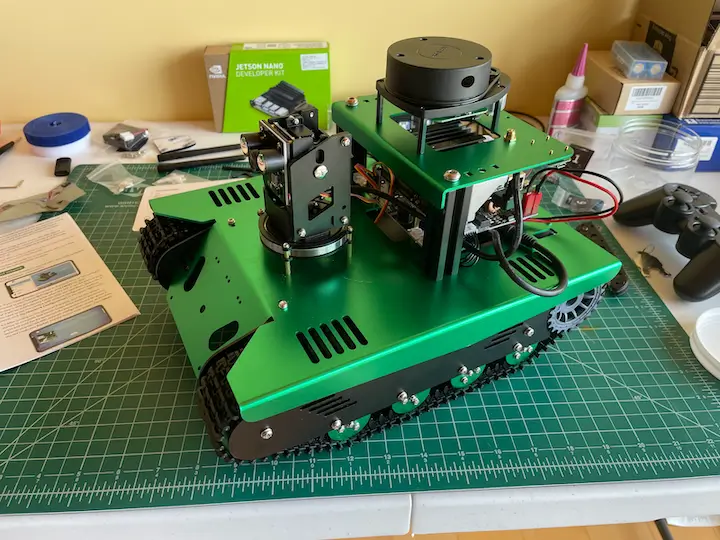
I really appreciated that the bot comes 90% assembled – this lets you get started with the platform without struggling through complex assembly instructions. For the rest, the instruction manual (Chinese and English) was relatively easy to understand, especially for a kit of this complexity. I was able to assemble the entire bot within an hour – this involved mounting the camera and LIDAR assembly, the expansion board, and Jetson NANO on top of the base.
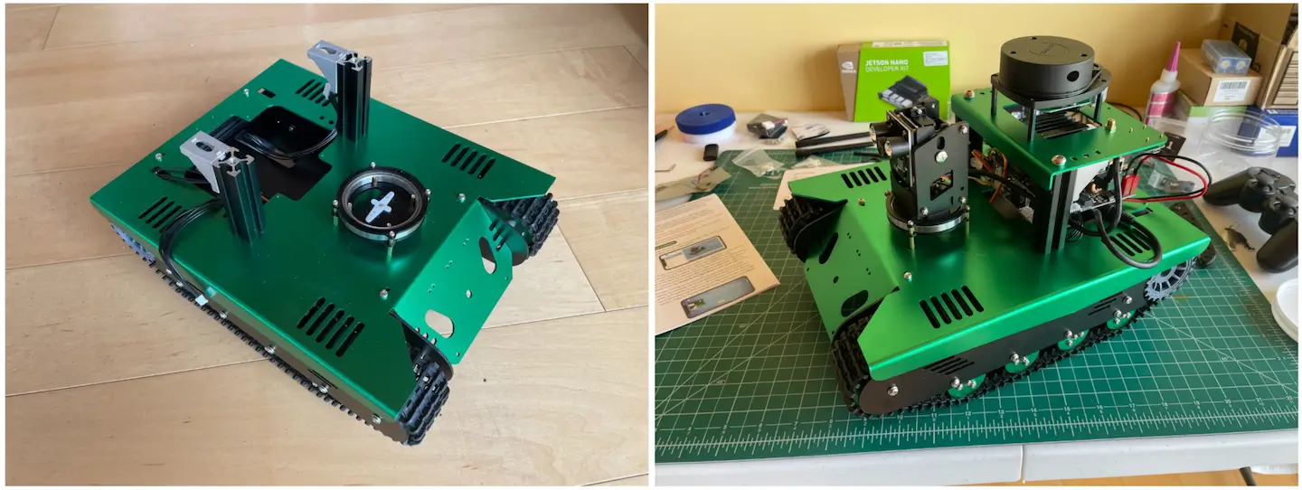
The Transbot base as shipped vs. after assembly.
Connecting your Transbot to Foxglove
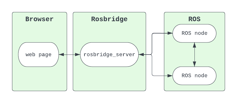
After assembling the physical hardware components, I realized that I needed software to help me understand what my robot was seeing and doing. I decided to connect my Transbot to Foxglove, a cross-platform robotics visualization tool compatible with many robotics platforms, to inspect and debug my robot as I went.
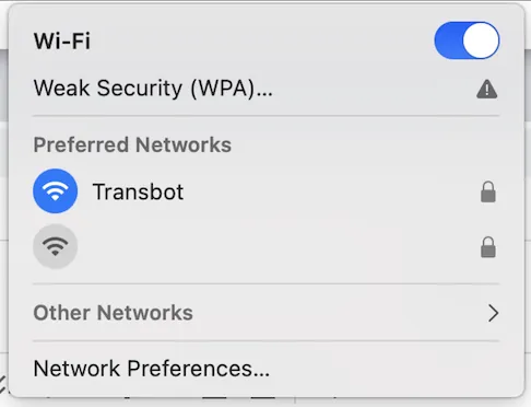
By default, the Transbot sets up a Wi-Fi network. By connecting my laptop to this same network (“Transbot”), I am ready to talk directly to my robot’s ROS system and inspect it with Foxglove.
Download the Foxglove desktop app – use the dialog that appears on app open to open a new ROS 1 connection (Open connection → ROS 1):
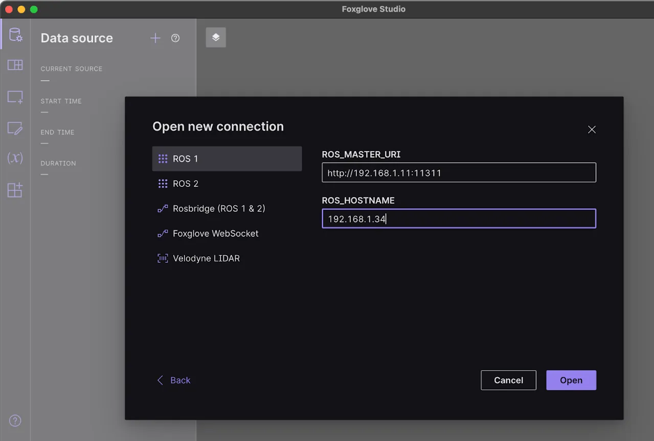
The ROS_MASTER_URI should be set to your Transbot’s IP address. The ROS_HOSTNAME should be set to your laptop’s IP address on the “Transbot” WiFi network – this is how your bot’s ROS nodes will send data to Foxglove on your laptop.
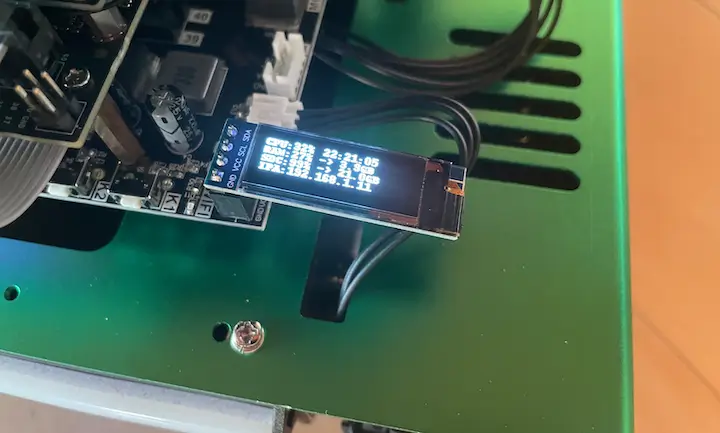
Check your Transbot’s OLED screen for its IP address.
You’re now ready to start visualizing your robot’s data!
Visualizing your Transbot’s data in Foxglove
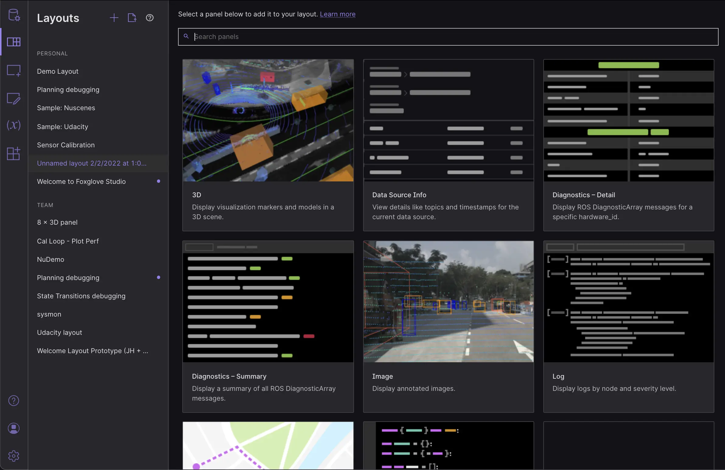
In Foxglove, let’s create a layout of panels that we’ll use to visualize data our bot data. Open the Layouts menu from the app’s sidebar, and add a new layout.
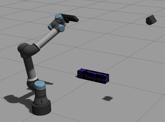
Next, let’s add a 3D panel to this newly created layout to visualize the Transbot’s LIDAR data, which the Depth camera collects via a 360° scan around the robot. Open the Add panel menu, also from the app’s sidebar, to see a list of all available panels.
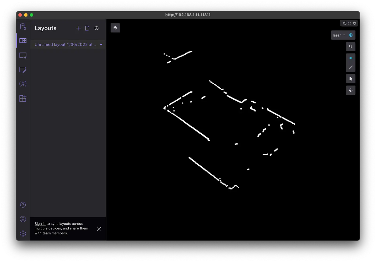
Once we’ve selected the 3D panel, let’s toggle on the /scan topic in the topic picker. Let’s also update the orientation controls on the right (base_link → laser), so we can view the LIDAR data from the POV of the sensor.
We now see the LIDAR from our robot! The raw scan details match the room my Transbot is in – I can see outlines of the walls, door, and random boxes, as well as the areas that the sensor isn’t able to “see”.
Before we drive the robot around with the included wireless controller, let’s set up some charts to plot the controller’s velocity commands. Again, using the Add panel menu, add a Plot and Raw Messages panel. The Plot panel will show me the history of values, while the Raw Messages panel will display the current value, for a given message path. In the Plot panel, let’s plot /cmd_vel.linear.x and /cmd_vel.angular.z over time. In the Raw Messages panel, let’s inspect the /cmd_vel topic.
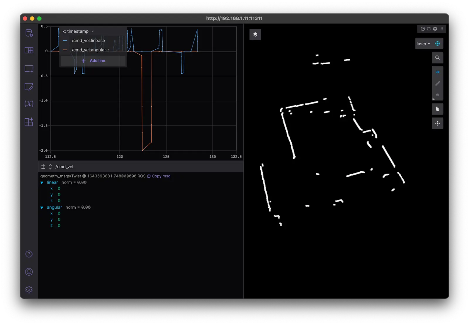
Now, driving the robot with your controller joysticks will publish those commands to the /cmd_vel topic. When moving the joysticks on the controller, we can see the values in the Plot and Raw Messages panels change.
Try adding other panels (like the Diagnostics and Log panels) to view other data being published by your robot!
Get support on your robotics journey
If you liked this review, be sure to also check out our review of Duckiebot, another educational robotics platform geared towards robotics beginners.
Whether your goals are to develop the next great SLAM algorithm, conduct vision processing, or build a new control loop, a robotics platform like Duckiebot or the Yahboom Transbot will give you a great jumpstart on the process.
Join us on Discord to ask questions, give feedback, and get other recommendations on the other robot kits you should try!