
About six months ago, a robotics engineering job opportunity I was excited about didn’t work out. Instead of letting that stall my momentum, I decided to invest directly in the skills I wanted to use every day. I bought a used Velodyne VLP‑16 on eBay and set a simple goal: learn ROS 2 and open-source SLAM by building something.
I’d been reading papers and exploring repos like FAST-LIO, KISS-ICP, and Cartographer, learning how modern SLAM systems work in theory, and how quickly they break when real-world conditions don’t match clean datasets. But I learn best by building. The VLP-16 felt like the right starting point: proven hardware, strong ROS support, and affordable enough on the secondhand market for a personal learning project.
The first experiments were immediately encouraging. I brought up ROS2 on a Raspberry Pi 5, got the VLP-16 driver running, and started playing with some of these open-source SLAM algorithms. Walking around my backyard with the sensor in hand, I could watch point clouds accumulate in real time. The algorithms worked. The maps looked coherent. I was learning fast.
But backyard testing wasn’t the end goal.
I’ve been caving for years. Tight passages, breakdown rooms, vertical sections, all the strange geometry you never see in a typical “office hallway robot demo.” Cave mapping is essential for navigation and conservation, but most surveys are still done the old-fashioned way: compass, clinometer, and tape. I kept coming back to the same thought:
SLAM could make cave mapping faster, richer, and more repeatable, but only if the sensor data is good enough.
That’s when I discovered what a 30-degree vertical field of view actually means in practice.
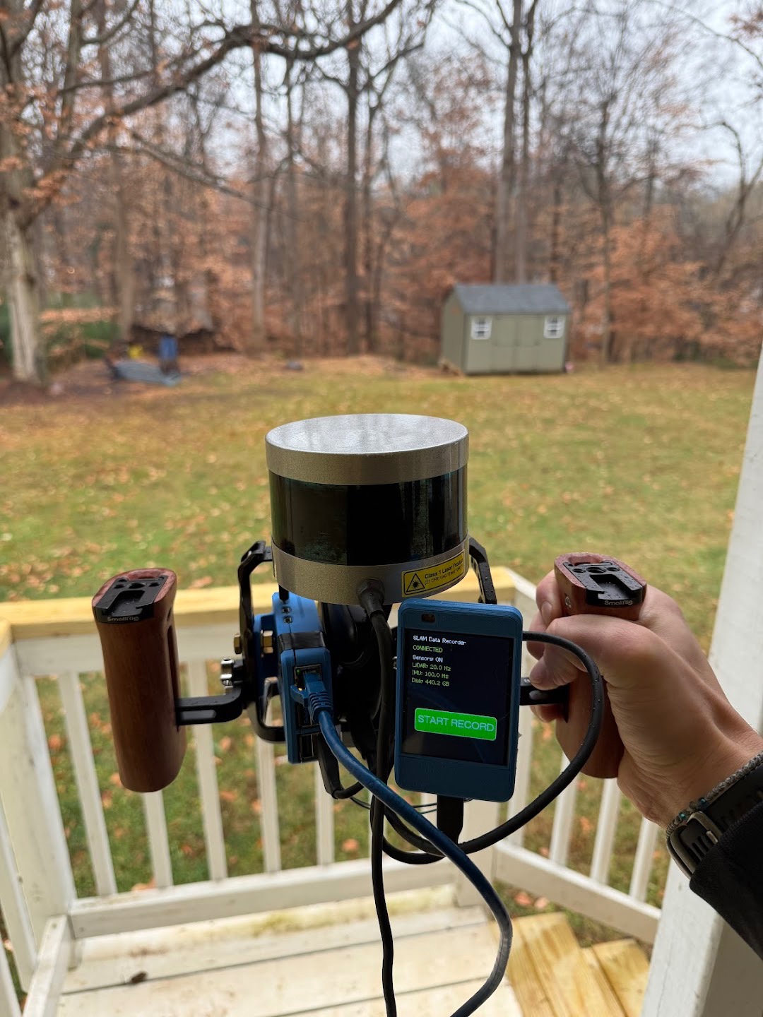
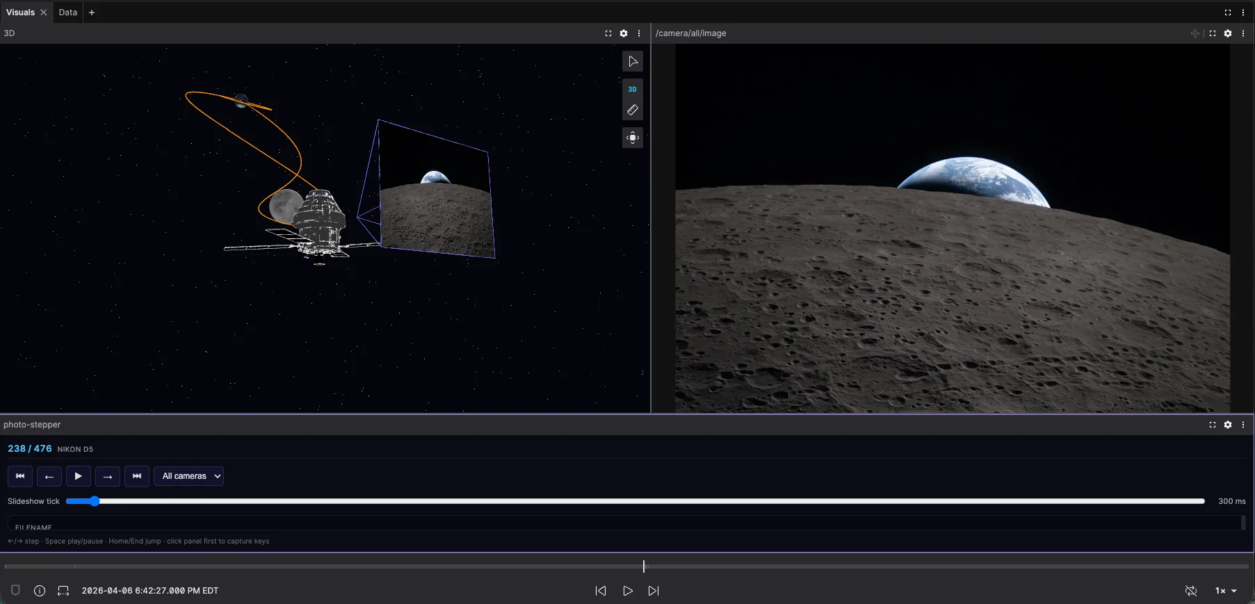
Handheld VLP‑16 backyard test
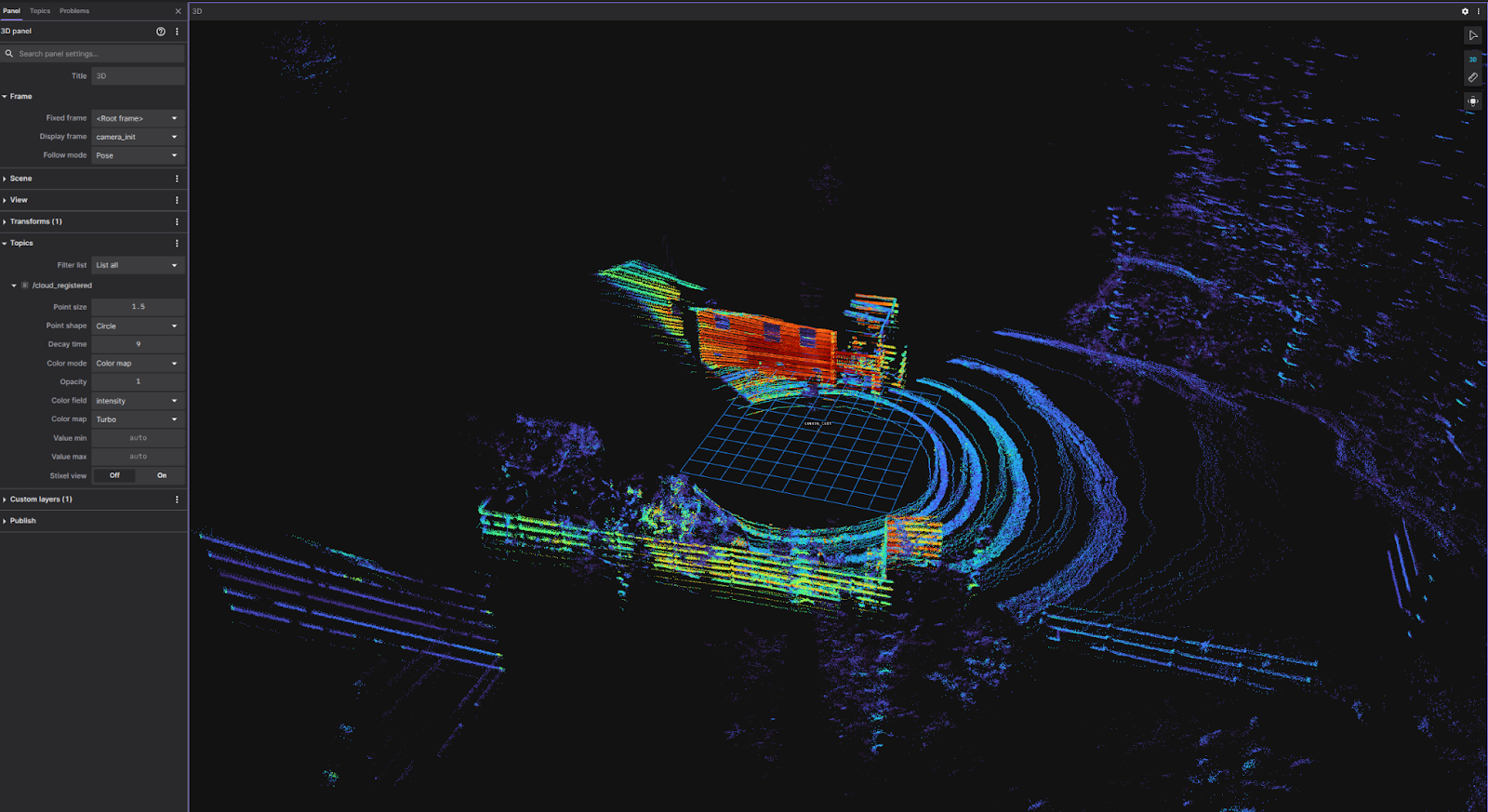
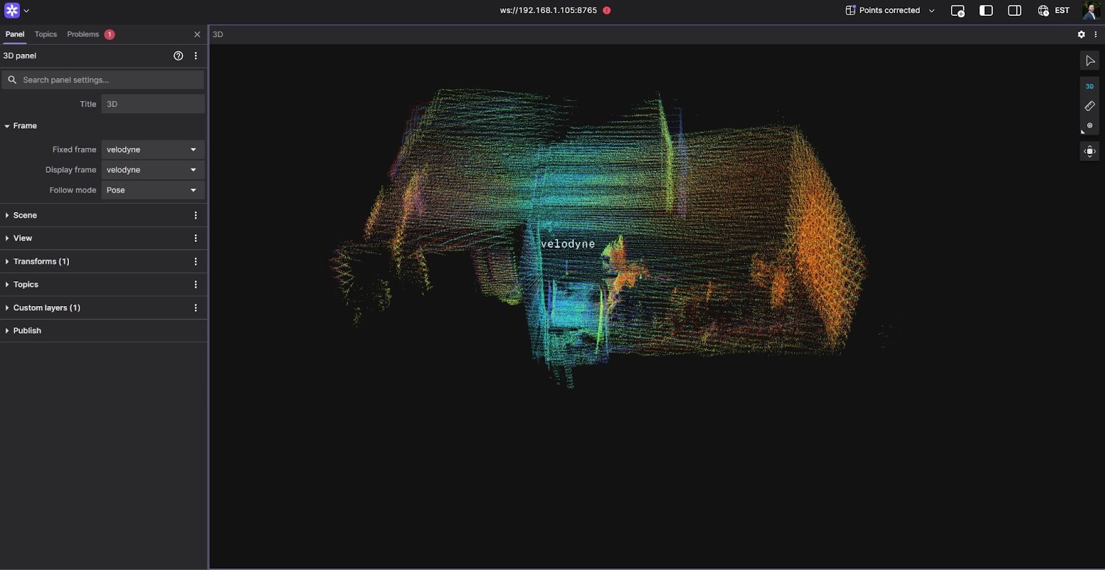
Screenshot of FAST-LIO point cloud accumulation with non-rotating VLP-16 in Foxglove
Understanding the VLP‑16 limitation
On paper, the limitation is simple: the VLP‑16 has 16 laser channels arranged vertically, spanning about +15° to −15°. This nets a 30° vertical field of view centered on the horizon. In structured environments with lots of vertical walls, that can be “enough.” A surprising amount of indoor geometry lives near the horizon line.
Caves are different. They’re inherently 3D environments where the most distinctive constraints often sit above and below the sensor: ceiling formations, overhangs, vertical shafts, and sharp floor changes. In many passages, the geometry that makes the space unique isn’t the mid-height rock wall. It’s the ceiling profile, the slope break, the pit edge, and all the “stuff” that lives outside of that 30° field of view.
Commercial systems like the Emesent Hovermap and research platforms using rotating LiDAR produced exactly the kind of data I wanted: complete spherical coverage with dense point clouds in all directions. My VLP-16 scans told a different story: a narrow horizontal band with massive vertical gaps. The VLP-16 was doing exactly what it was designed to do, but for cave mapping, I needed that kind of full spherical coverage. Just at a price point that made sense for a personal project.
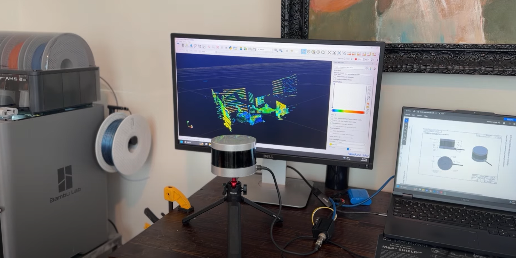
Raw VLP-16 point cloud
The Emesent Hovermap and similar systems proved the concept: rotate the sensor to sweep its narrow FOV through a full sphere, mechanically expanding coverage. Instead of buying a wider-FOV sensor, use motion to see more with what you have.
As a mechatronics engineer, this was exactly the kind of problem I wanted to tackle. My strengths are in mechanical design and electromechanical integration: motor control, packaging, reliability, the details that decide whether something survives field use. I was already pushing myself on the software side with ROS 2 and open-source SLAM algorithms. Building a rotating platform would let me attack the coverage problem from my mechanical skillset while learning how SLAM systems handle motion compensation and time synchronization.
The concept is simple: rotate the VLP-16 continuously so its narrow vertical slice sweeps through the full environment. The challenge is making that rotation smooth and precisely measurable, because any wobble or timing drift becomes point cloud distortion.
I used a 2404 BLDC gimbal motor with a 5:1 gear reduction for smooth, controlled rotation. SimpleFOC running on a Teensy 4.0 handles motor control. The critical piece is an AS5600 magnetic encoder providing angle feedback transmitted via UART to the Raspberry Pi 5. This encoder data is essential for deskewing the point cloud in the SLAM pipeline.
For signal routing, I used a power + ethernet slip ring to handle the VLP-16’s data connection plus power conductors for continuous rotation without cable wrap.
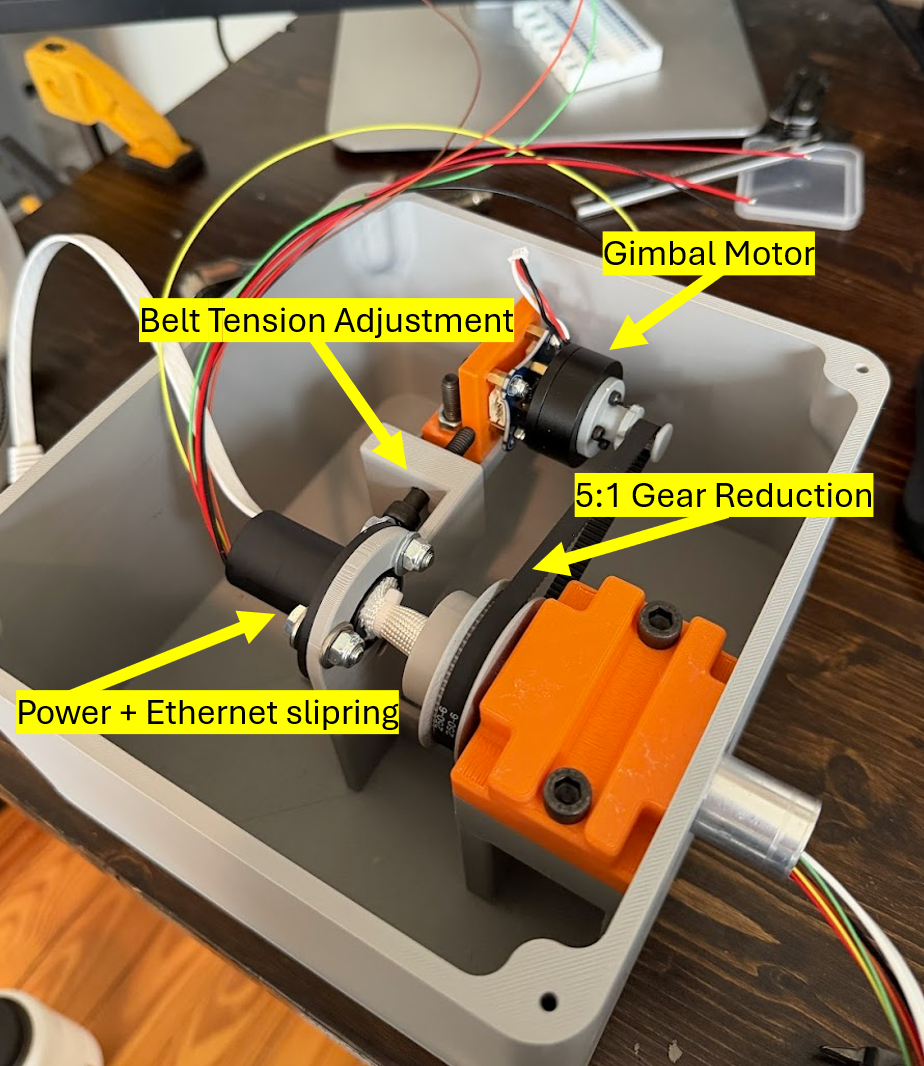
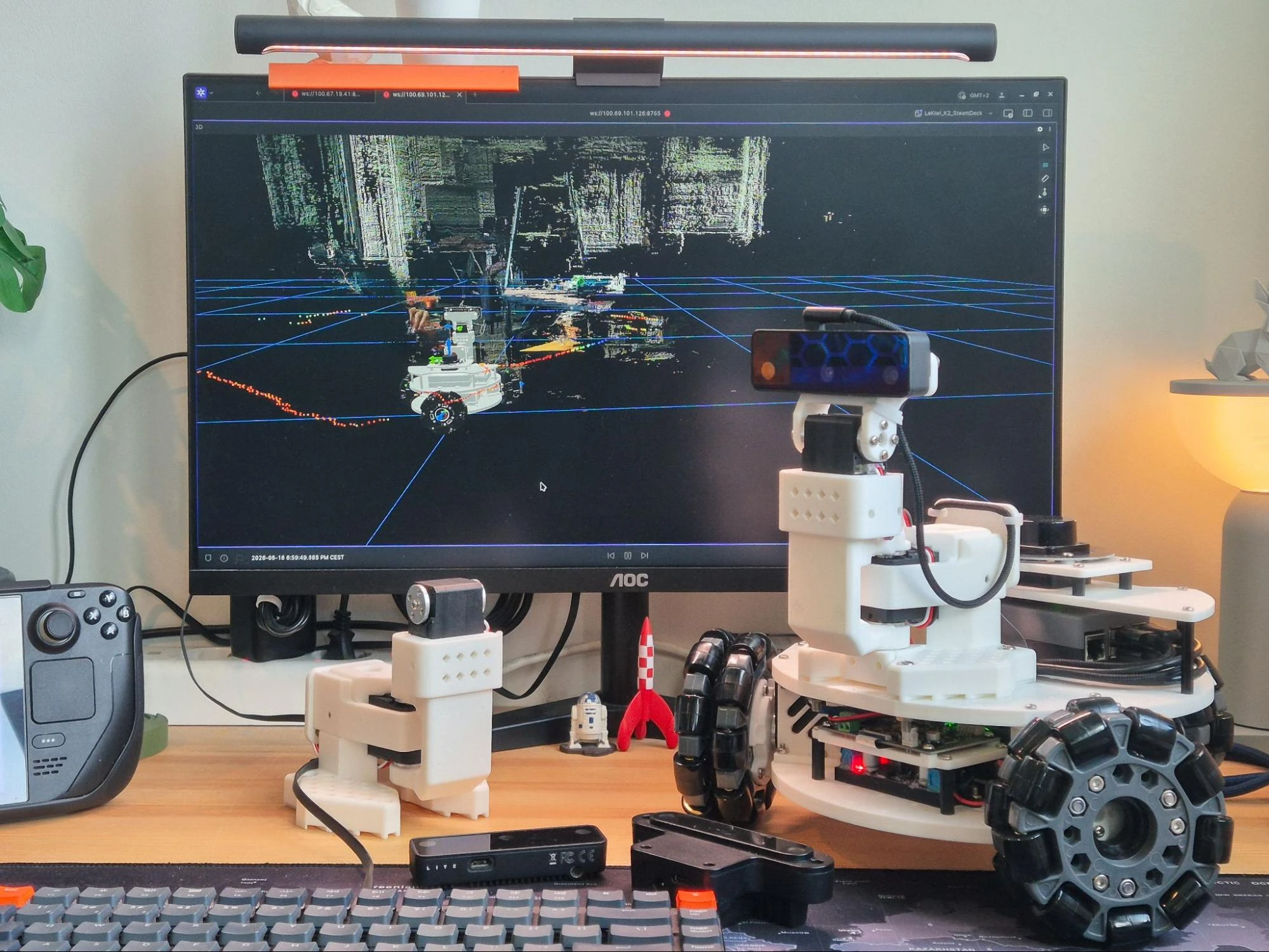
Rotating platform
The critical piece: encoder-based deskewing
Mounting LiDAR on a rotating joint breaks a key assumption most SLAM pipelines rely on, that the sensor is rigidly fixed. Since a LiDAR scan isn’t instantaneous (points accumulate over a time window), ignoring platform rotation during that window creates motion artifacts: curved walls, smeared corners, fuzzy edges. Those distortions erase the geometric constraints SLAM needs to stay stable.
The fix: deskew the point cloud using encoder angle. For each LiDAR packet, interpolate the AS5600 angle at that timestamp and rotate points into a common reference before feeding them to the mapping pipeline. With a rotating mount, point cloud quality is fundamentally a synchronization problem. Get angle(t) right and the map snaps into focus.
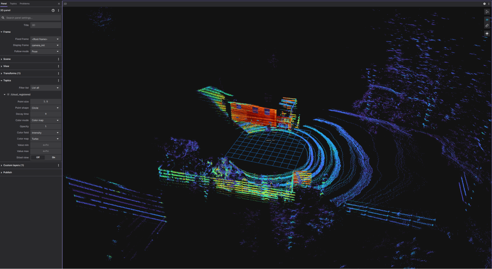
Foxglove made this quick iteration possible
Debugging timestamp alignment and deskew quality blind would have been painful. Foxglove gave me a live “truth window,” a 3D point cloud view alongside encoder angle/velocity plots, so I could correlate cause and effect immediately. Tuning rotation speed or tweaking compensation? I could see whether geometry improved or just looked busy, all while SSH’d into the Pi from Windows. That tight feedback loop turned what could have been days of guessing into fast, confident iteration.
Foxglove layout used during tuning
What’s next
Cave testing is the obvious next step, and where I expect to learn the most. Experimenting with different rotational speeds and how it can affect stability in narrow, feature-sparse passages. How does the system hold up over longer runs? What about dust, humidity, and real-world handling? I’m also curious whether different rotation strategies make sense.
Before heading underground, I’m also planning a redesign of the enclosure. The current setup works fine for backyard testing, but caves demand something more rugged: better sealing against dust and moisture, improved cable management, a more compact form factor for tight squeezes, and overall durability for the inevitable bumps and scrapes.
Beyond that: tighten calibration and repeatability, and eventually package the build so others can replicate it.
Closing thoughts
This started as a learning project. I bought a VLP-16 to learn SLAM by building, and quickly hit a real limitation for the environments I care about. A rotating platform turned out to be a surprisingly effective way to trade mechanical complexity for expanded coverage.
Cave tests are next. But even before that, the build has already done what I wanted: force me to understand how sensing, motion, timing, and mapping actually fit together. In the real world, those details are the system.
About the Author
Tyler Thomas is a mechatronics engineer with over five years of experience in commercial vehicle development, most recently focused on hydrogen fuel cell and battery electric powertrains. Outside of work, he’s passionate about robotics and SLAM, building LiDAR-based cave mapping systems as a way to combine his love of caving with his engineering skills. He’s currently looking to transition into the robotics and autonomous systems industry.