Calibrating a monocular camera for the LeKiwi robot using ROS 2
tl;dr This article details my process of calibrating a USB webcam for the LeKiwi robot. Due to constraints, I was unable to use the standard ROS 2 camera calibration process, so I modified the original camera_calibration node to run remotely and without a display - logging progress to the terminal and saving results automatically on exit. With this, Foxglove’s Image and 3D panels, I was able to validate the calibration process and the results. The result is a calibrated camera and a completed perception stack, now ready for autonomy.
Project Context
I purchased a LeKiwi mobile robot kit late last year - an omnidirectional platform originally designed for the LeRobot framework - and have been gradually rebuilding it to run autonomously with ROS 2. The first major addition was a LiDAR, which I covered in my previous post. Alongside that, I worked on the URDF and set up the motion control using ros2_control.
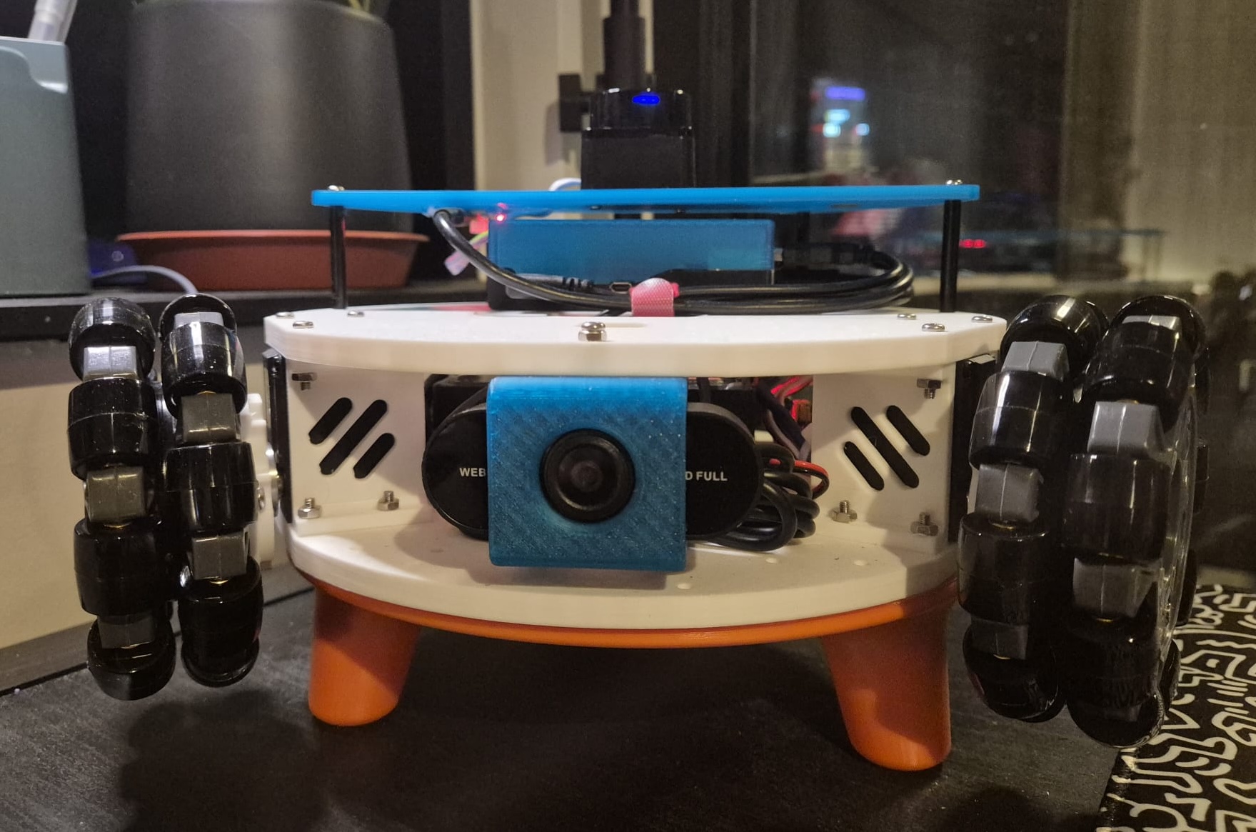
The next piece of the puzzle is the camera. LeKiwi includes a camera on the mobile base, and I’m using a cheap, generic webcam that fits perfectly with the mount the kit shipped with. Before it can be useful for anything beyond a live video feed, it needs to be calibrated. This post explains how I achieved this to complete the perception stack for the robot.
Why do we even need Calibration?
Every camera lens bends light slightly differently. Cheaper webcams (like the one I’m using on LeKiwi) often introduce significant barrel distortion, making straight lines appear curved, especially near the edges of the frame. This might be barely visible when streaming images, but it’s a nightmare for robotics applications that require accurate depth perception, object detection, or visual odometry.
This is where camera calibration comes in. It is the process of determining the camera’s mathematical properties: its focal length, optical center, and lens distortion characteristics. These “intrinsic parameters” describe how it transforms the 3D world into a 2D image, and can be used by robotics applications to mathematically correct the lens imperfections.
Camera Calibration 101
Camera intrinsics are captured in a camera matrix (also called the intrinsic matrix), which contains:
- Focal length (fx, fy): The scaling factor between 3D scene coordinates and 2D image pixels - two values to account for potentially non-square pixels
- Principal point (cx, cy): The optical center of the image (usually near the middle, but not always!)
The intrinsic matrix K is defined as a 3x3 matrix:
    [fx  0 cx]
K = [ 0 fy cy]
    [ 0  0  1]
Additionally, the calibration process generates:
- Distortion coefficients: Parameters that model radial and tangential lens distortion, depending on the distortion model used, like
plumb_boborrational_polynomial. - Rectification matrix: Rotation matrix for aligning stereo images (for stereo cameras only)
- Projection matrix: Intrinsic matrix of the projected (rectified) images
In ROS 2, this information lives in a sensor_msgs/msg/CameraInfo message, which camera drivers publish alongside image data. Downstream nodes, such as those performing visual odometry, for instance, subscribe to both the raw image topic and the camera info topic, and correct for distortions internally.
The “official” ROS 2 calibration process
The standard approach in ROS 2 uses the camera_calibration package with a printed checkerboard pattern. Here’s the workflow:
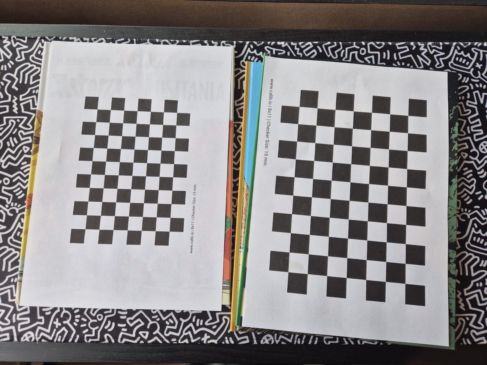
- Print a checkerboard: You’ll need a checkerboard pattern with known dimensions. Make sure it’s mounted flat on a rigid surface. Calib.io has a really intuitive pattern generator that I used to print my checkerboard patterns.
-
Launch the calibration node: Run the calibrator from the
camera_calibrationpackage, specifying your checkerboard dimensions and camera topics. -
Move the checkerboard: Move the board around to capture diverse angles - left, right, top, bottom, tilted, close, far. The calibration GUI shows progress bars that track coverage across the X, Y, and size dimensions. Hold each position until the window highlights the captured frame.
-
Calibrate and save: Once you’ve collected enough data, hit the Calibrate button. After processing, review the undistorted result, then save the parameters to a YAML file, which you can then load into your camera driver using the
camera_info_urlparameter.
The full tutorial with detailed instructions is available in the ROS documentation: ROS 2 monocular camera calibration tutorial.
How I actually did it
The official calibration process provides a GUI that needs a display, which I don’t have since I’m running the LeKiwi on Ubuntu Server without a desktop GUI installed. I also cannot find my USB-A to USB-C adapter, so I can’t even connect the camera to my laptop directly. So I had to get creative. I copied the camera calibration script to my laptop and modified it to run “headless”.
To do this, I copied the original camera_calibration script and updated it to display coverage and progress information in the terminal rather than the GUI window. I then added the calibration and commit steps to the termination handler, so that once I had collected enough data, I could simply stop the script and it would automatically calibrate and save the parameters. This script can be found as a GitHub Gist here. It is a hacky solution, but it got the job done without needing any fancy setup.
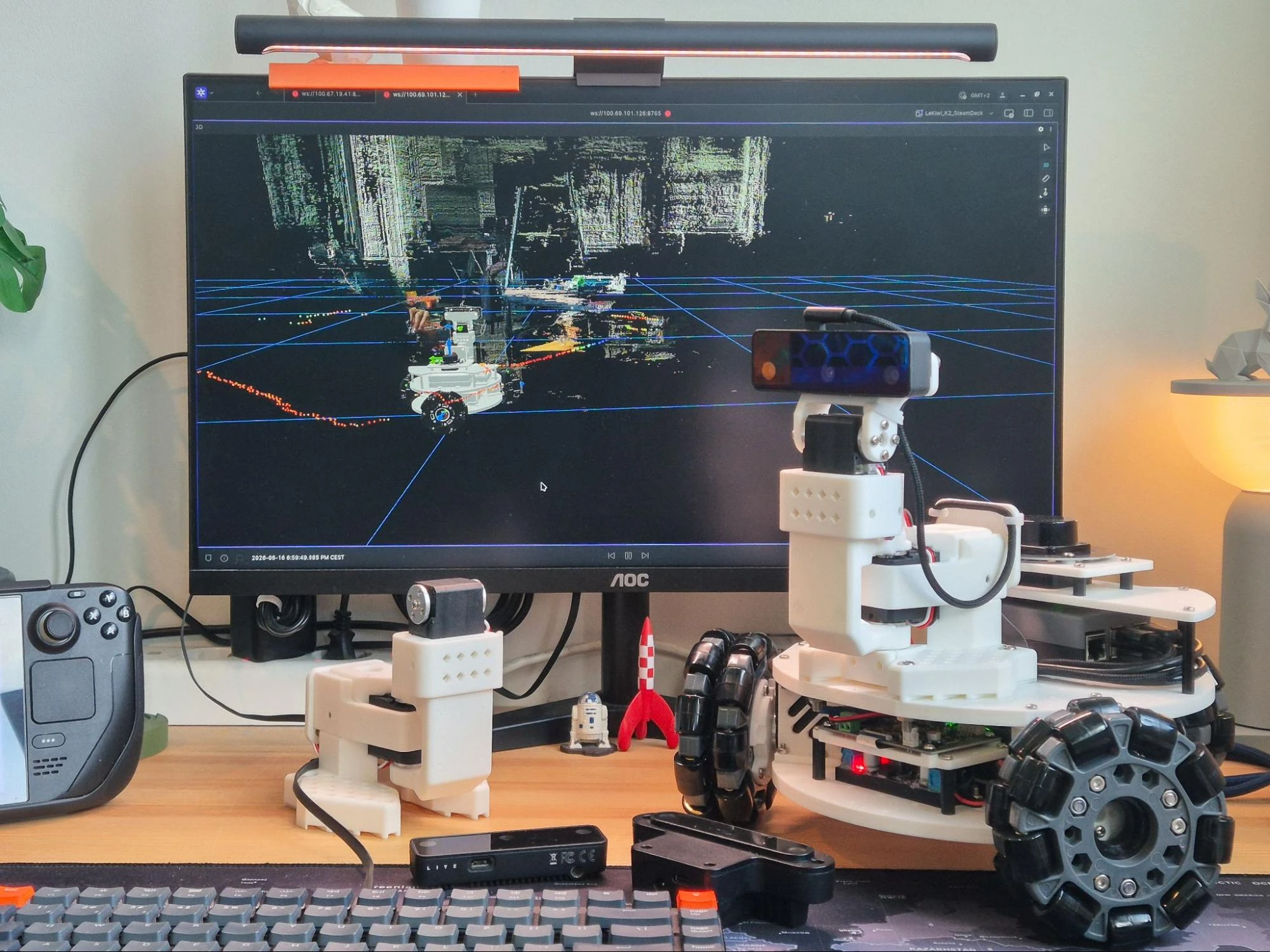
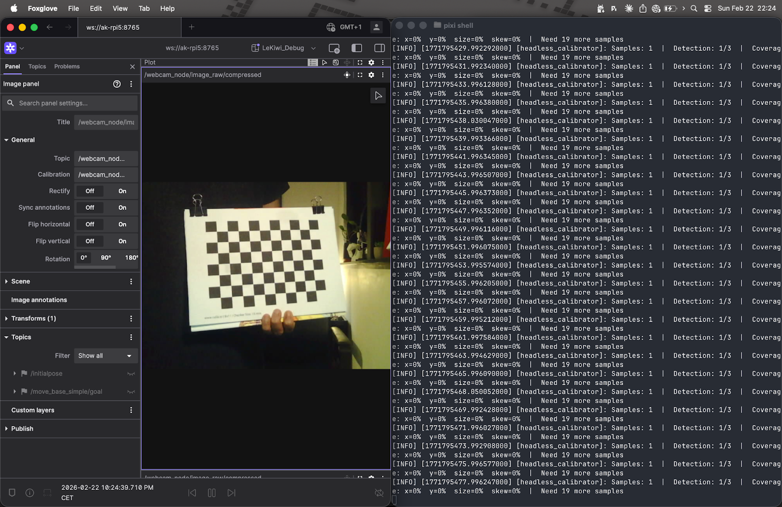
For visual feedback, I used Foxglove and its Image Panel to visualize the camera feed, while I moved the checkerboard around in front of the camera and monitored the terminal output on the side. LeKiwi’s Raspberry Pi and my laptop were on the same Wi-Fi network and using Zenoh for communication. For Foxglove, I simply started the Foxglove bridge on the Raspberry Pi and connected to it from the Foxglove app on my laptop.
Implementation note: I only did this headless hack out of necessity. If you can do it using the normal GUI method, I would recommend it. However, if you are in the same situation as me and want to try out this headless mode, make sure you have a stable internet connection and that your camera is publishing images at a decent frame rate.
What’s really happening under the hood
Both implementations share the same core calibration math. For each captured frame, OpenCV locates the checkerboard corners and then performs a non-linear least-squares optimization to find the camera matrix K and distortion coefficients D. The results are saved as a YAML file containing the camera matrix, distortion coefficients, rectification matrix, and projection matrix.
The main difference is in quality control. The official GUI tool lets you see detected corners in real-time, and expects you to hold the checkerboard still, so you naturally avoid capturing blurry or poorly-lit frames - the human is the filter. Without a display, my headless script can’t do that, so it compensates algorithmically: it detects and removes outliers, then re-runs calibration on the cleaned dataset.
There are also minor differences in the OpenCV functions used: The original method uses findChessboardCorners + cornerSubPix for corner detection, my method uses findChessboardCornersSB. The original uses calibrateCamera; mine uses calibrateCameraExtended, an extended version that provides additional data, which I then use for outlier detection. That said, the underlying math is identical.
The detailed explanation about camera calibration can be found in the OpenCV documentation here.
Spot the difference: before and after calibration
With the calibration file in hand, it’s time to put it to use. I saved the camera.yaml output from calibration into the lekiwi_bringup/config/ directory. Then I updated the webcam.launch.py launch file (from the camera_ros package I’m using for the USB webcam) to load the calibration parameters via the camera_info_url parameter.
Now, when the camera node launches, it publishes:
- Raw images on
/camera/image_raw - Compressed images on
/camera/image_raw/compressed - Camera intrinsics on
/camera/camera_info
Any downstream node that needs geometrically accurate images can subscribe to both the image and camera_info topics and apply undistortion. For visualization in Foxglove, I used the compressed image stream, which is more bandwidth-efficient.
Foxglove’s Image Panel makes it trivially easy to visualize the impact of calibration. The panel has a Rectify toggle that, when off, shows the raw or compressed images straight from the camera, and, when on, applies rectification using the camera_info message.
The difference is pretty subtle on this particular camera. The barrel distortion isn’t severe enough to be immediately obvious in casual viewing. However, for applications like visual odometry or fiducial detection, even subtle distortions can throw off measurements by centimeters or more. If you use a fisheye lens, for instance, the rectification makes a dramatic difference.
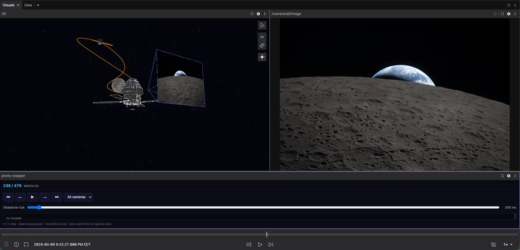
Visualizing in 3D
While the Image Panel is great for inspecting rectification, Foxglove’s 3D Panel takes things a step further - it can render the camera feed directly in 3D space, anchored to the camera’s coordinate frame. Since LeKiwi’s URDF already defines a fixed joint between the camera and the robot body, the camera image is automatically positioned and oriented relative to the robot, so you can see the camera’s view from the correct position and perspective within the full 3D scene.
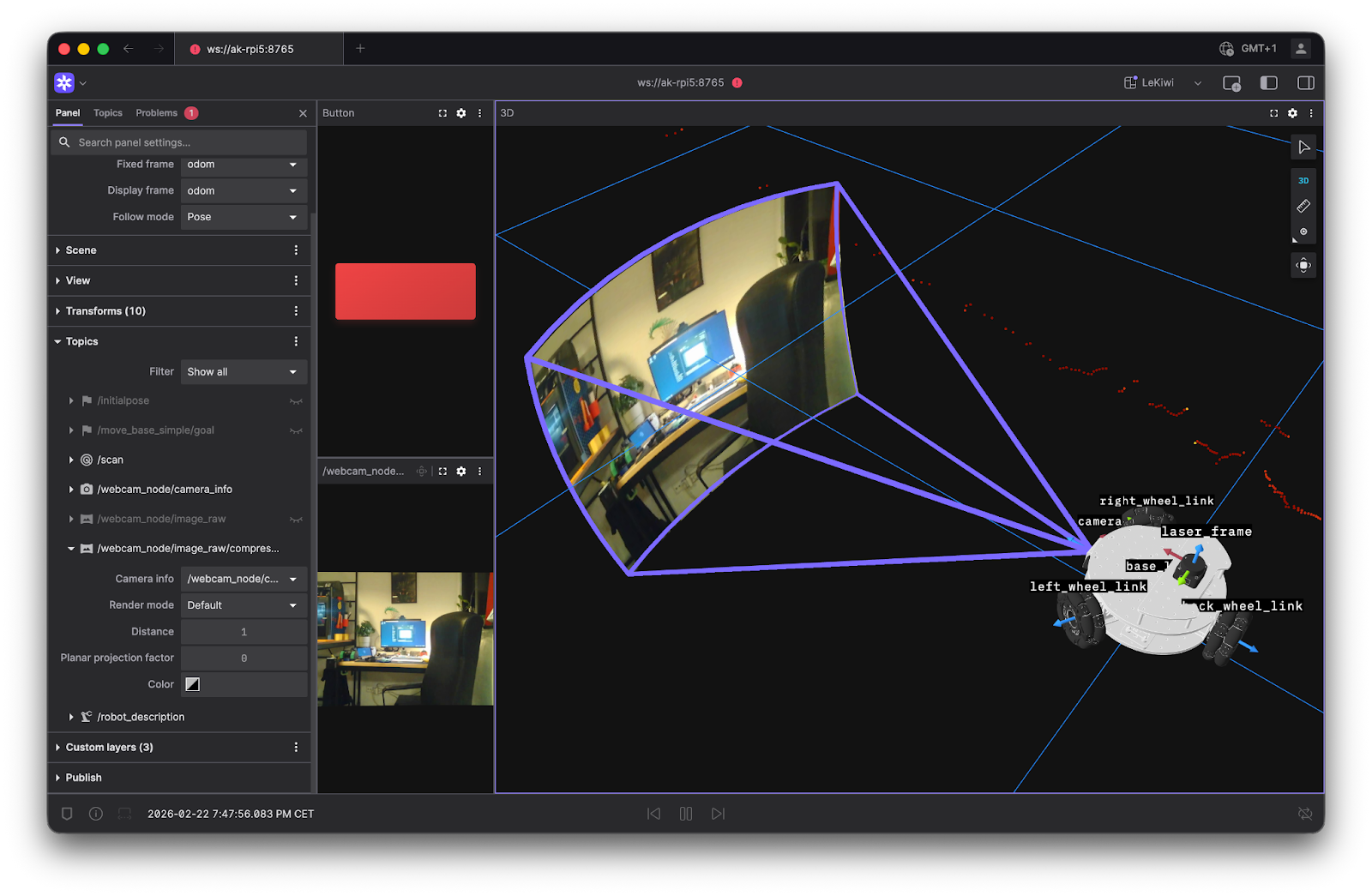
In the image above, the 3D panel renders the /camera/camera_info topic as a frustum in the scene, showing the camera’s FOV. It then renders the actual camera images, either raw or compressed, on that frustum. This is a surprisingly satisfying sanity check.
In addition to the default perspective projection, the 3D panel offers a couple more ways to render images.
- The plane projection option projects the image on the XY plane. This is quite useful when you have a large FOV, like with fisheye lenses. Here’s an example of the plane projection mode in action:
Try it yourself by changing the render mode of the cameras in this example.
- The depth map option renders a depth image as a pointcloud in 3D space. This does not apply to the LeKiwi, since it uses a monocular camera.
Wrapping up
Camera calibration isn’t the most glamorous part of robotics, but it’s one of those foundational steps that quietly enable everything else. And throughout this process - from waving a checkerboard at a robot to verifying rectification results - using Foxglove made the whole thing significantly less painful.
With the camera now calibrated and ready for use, the LeKiwi is starting to feel like a real robot. Between my earlier article about integrating the LiDAR and this one, the pieces are coming together. The perception stack is now in place, the URDF is ready, and the ros2_control integration is nearly complete, with some final tuning left. Soon, I will be ready to dive into autonomous navigation with Nav2.
My work on the ROS 2-powered LeKiwi is available on GitHub. It’s very much a work in progress - new features will be added and existing ones improved as the project evolves. That said, feedback and contributions are always welcome!