
This article details my process of upgrading a LeKiwi robot - a low-cost, open-source mobile manipulator - with a 2D LiDAR sensor and ROS 2 to enable SLAM and autonomous navigation. The process involves hardware integration of the LiDAR, creation of the URDF and a ros2_control package, and teleoperation, all of which were tested using Foxglove. The result is a functional ROS 2-powered, LiDAR-equipped mobile base, currently driven by a game controller, but fully ready for autonomous exploration.
A few months ago, I purchased a LeKiwi robot kit to explore the LeRobot framework and create embodied AI applications. However, my experience at ROSCon 2025 in Singapore was a turning point, inspiring me to build with ROS once again, so I decided to repurpose the LeKiwi platform for this journey. With my sights set on using Nav2, the navigation stack for ROS 2, I decided to add a 2D LiDAR to the mix. In this article, I will guide you through my workflow and explain how Foxglove was a crucial tool at various stages of my design process.
What’s LeKiwi?
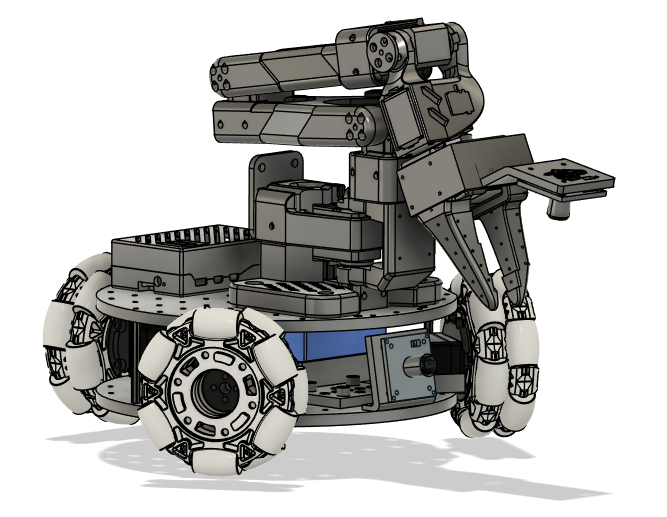
Launched in early 2025 by SIGRobotics, a student group from the University of Illinois Urbana-Champaign, LeKiwi is a low-cost, open-source mobile manipulator. Designed to pair seamlessly with LeRobot, HuggingFace’s robotics framework for physical/embodied AI, it features an omni-wheeled base, a camera, a Raspberry Pi 5, and mounting points for the popular SO-101 robot arm. The base and arm share the same STS3215 serial bus servo motors, making integration with existing LeRobot setups a breeze.
With the growing popularity of LeRobot, it became an instant hit, especially among people who already had an SO-arm. Several companies also started offering fully assembled and DIY kits with everything you need. I was already on the hunt for a new robot platform, and since I already had experience with the SO-100 and the STS3215 motors, I couldn’t resist. So, I grabbed a kit to see what the buzz was about.
Why add the LiDAR?
After I changed directions and decided to work with ROS 2 and Nav2, which need localization and mapping data for autonomous navigation, adding a LiDAR was a no-brainer. Packages such as slam_toolbox can be used to create a map from the laser scans and then localize the robot within it. First, I set the arm aside temporarily and zeroed in on the mobile base.
With or without ROS 2, adding the LiDAR was a smart move. The LeKiwi base has a front-facing camera, and even with an SO-101 arm with a wrist-mounted camera attached, the rear is still a blind spot. A simple 2D laser scanner offers a budget-friendly way to achieve 360-degree obstacle detection. Even when an arm is attached, and parts of the laser scan are obstructed, the robot’s blind spots are still covered.
Integrating the LiDAR
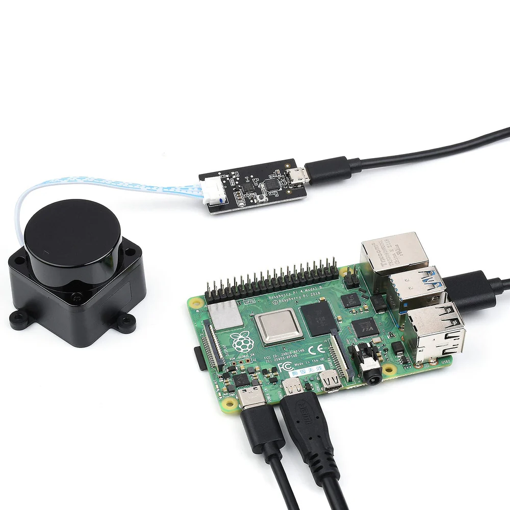
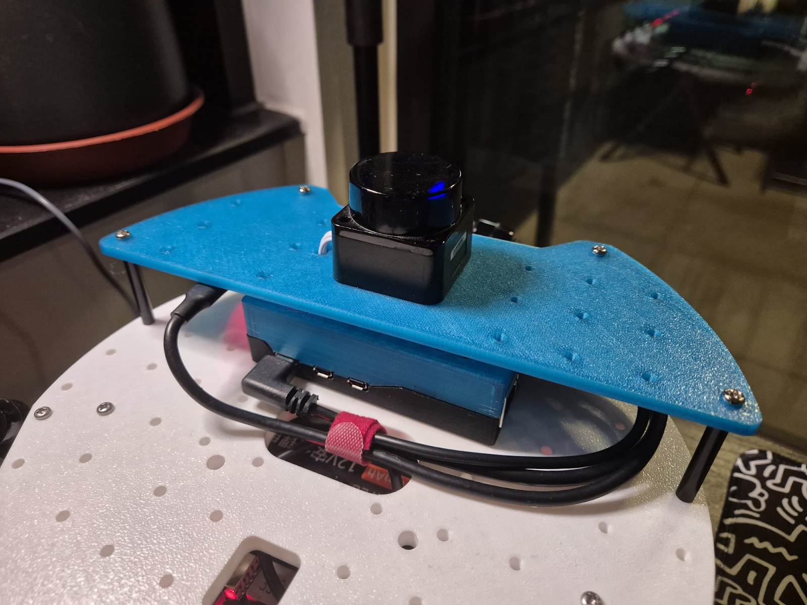
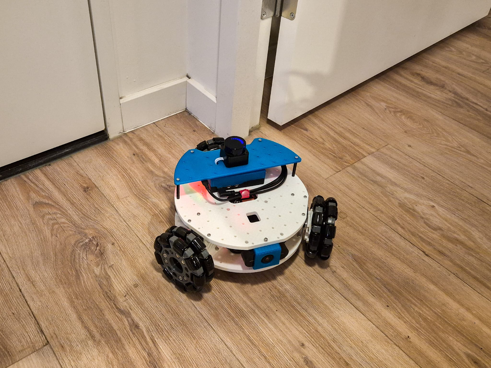
I used my spare LD19 LiDAR and quickly designed and 3D printed a mounting plate. The sensor was now secured, with the USB adapter glued underneath. I then used four 35mm spacers to attach it above the Raspberry Pi. I eventually want to reattach the SO-101 arm, so I made sure to leave the mounting spot for it untouched. Finally, I connected the adapter to the Raspberry Pi with a USB cable.
Next, I tested the setup using the LDLidar ROS 2 package provided by the manufacturer, rather than other available alternatives. It wasn’t the best choice, as the package had several bugs. But with AI tools at my disposal, fixing them was a breeze. I have pushed these fixes to my working fork of the LDLidar ROS 2 package.
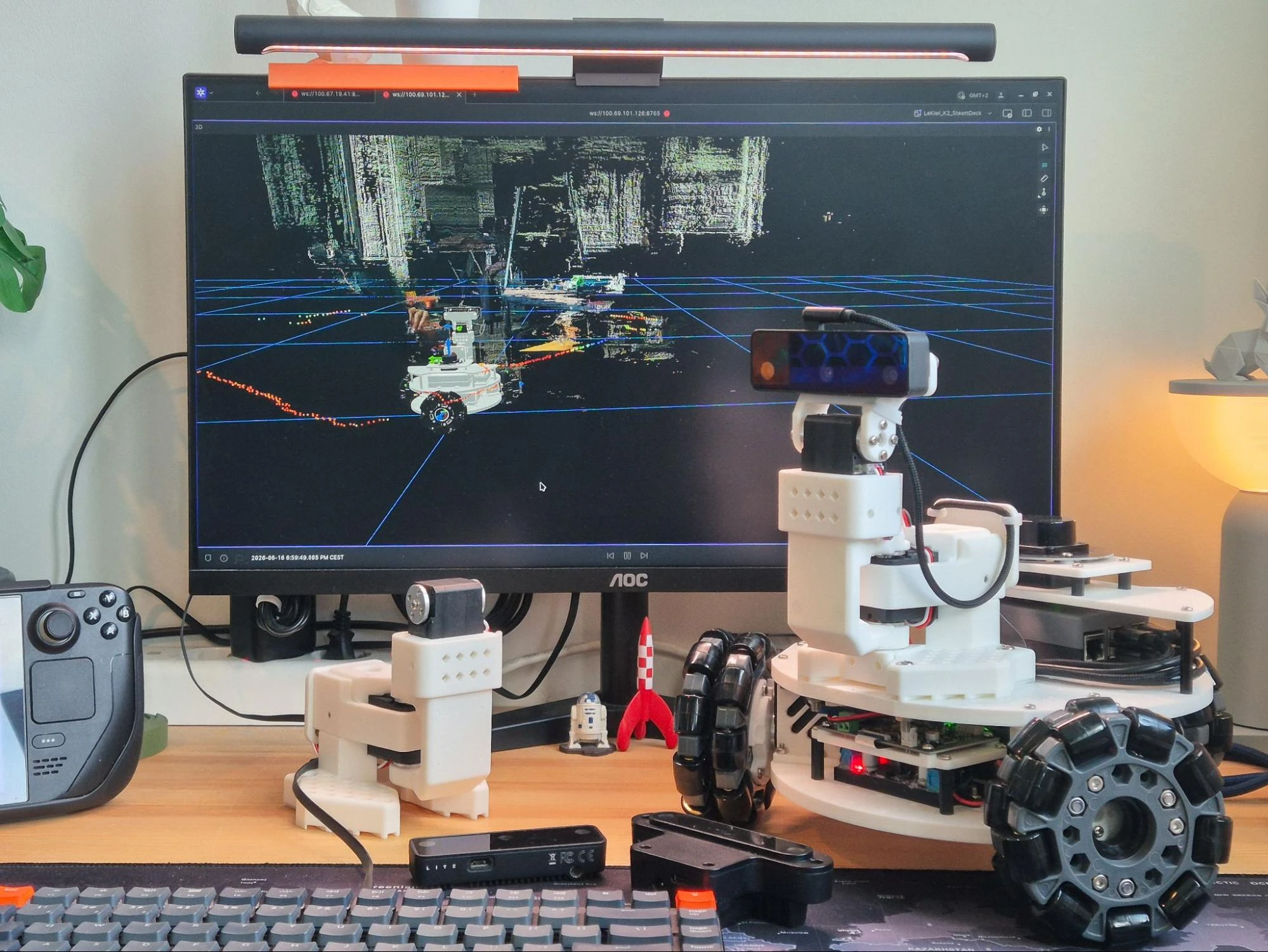
Finally, it was time to visualize and test the LiDAR using Foxglove. I ran the following commands on separate terminals on the robot’s Raspberry Pi.
ros2 launch ldlidar_ros2 ld19.launch.py

ros2 launch foxglove_bridge foxglove_bridge_launch.xml
On my laptop, which is on the same network as the Raspberry Pi, I simply launched the Foxglove app, connected to the Foxglove Bridge on port 8765, and the laser scan visualization appeared on the 3D panel right away.
URDF and ROS 2 Control
Aided by AI, I set off to create my own LeKiwi ROS 2 package, following these steps:
First, I tackled the robot description file (URDF). It defines the robot’s links and joints and maps them to the correct mesh files for visualization. The URDF also allows for adding ros2_control tags to specify command and state interfaces, along with actuator limits. Since the LeKiwi repository contains an older version of the URDF, I created a new one for my robot and made it public in the lekiwi_description package.
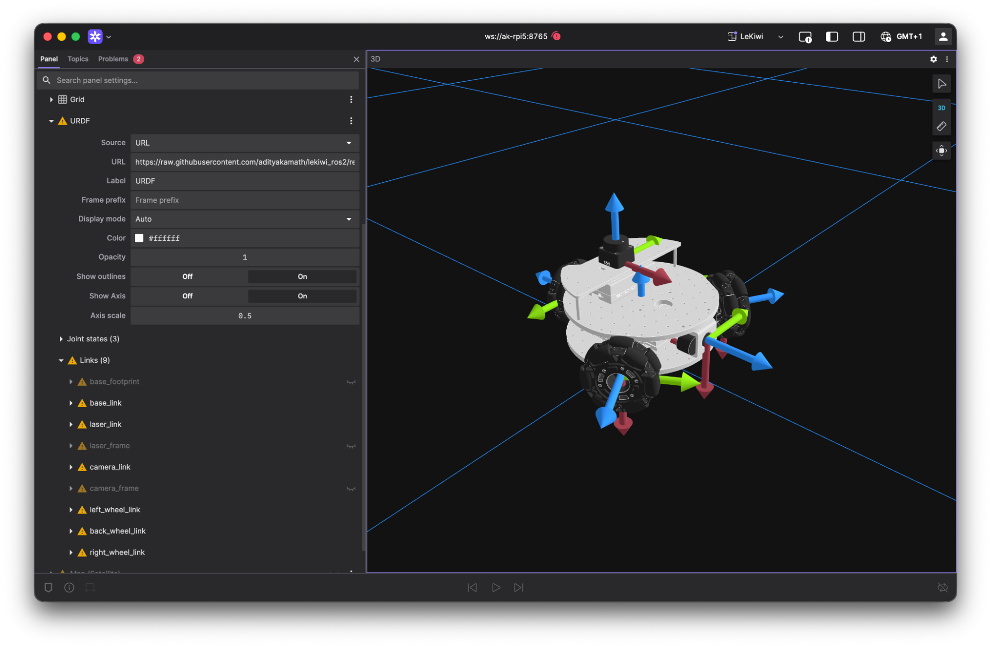
Foxglove was quite helpful in visualizing the URDF. The 3D panel provides an option to add a custom URDF layer, which requires a link to a URDF file (URL, ROS 2 parameter/topic, or local path).
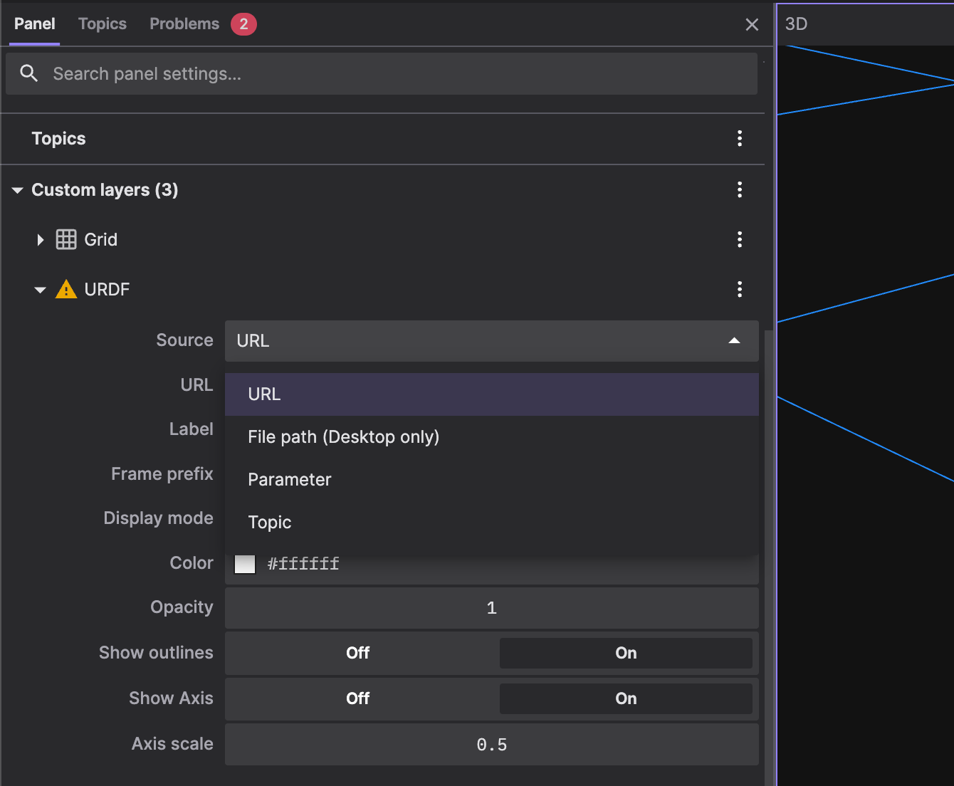
I used the URL to the raw URDF in my GitHub repository, which you can try out yourself without a local ROS 2 installation.

As shown in the image, I’ve also included the links and meshes for the LiDAR and the Camera, which I plan to implement later. Note that the warning signs in the above images are due to my visualizing a static URDF from a URL and not having a live connection to the robot at the time of testing.
With the robot’s links, joints, and meshes visualized correctly, the next step was to control the motors and move the robot. For this, I used ros2_control. I created a hardware interface for the STS3215 motors and then configured the omni_wheel_drive_controller, which is provided in ros2_control.
You can find my implementation of the hardware interface and control configuration in the sts_hardware_interface and lekiwi_control packages, respectively. Note that the hardware interface was extensively tested only with the STS3215 motors. Please proceed with caution when using other STS series motors or untested modes (such as servo or PWM mode).
I tested everything using Foxglove, making adjustments to the control configuration and URDF along the way. On the Raspberry Pi, I used three separate terminals to run the controller, the Foxglove bridge, and a TwistStamped publisher (the controller requires twist messages with a timestamp) using the following commands:
ros2 launch lekiwi_control base.launch.py

ros2 launch foxglove_bridge foxglove_bridge_launch.xml

ros2 topic pub -r 10 /base_controller/cmd_vel geometry_msgs/msg/TwistStamped "{  header: {frame_id: 'base_link'},  twist: {linear: {x: 0.1, y: 0.0, z: 0.0}, angular: {x: 0.0, y: 0.0, z: 0.0}}}"
And here are the results:
In this video, the robot is placed on a platform, so the motors are moving, but the wheels are not touching the floor. This means that the odometry, computed from the measured velocities of each motor, is quite accurate. With this test, I validated the URDF and the default control setup before integrating with the LiDAR.
Integration and Testing
To integrate the control package with the LiDAR, I set up a combined launch file in lekiwi_bringup. This launch file starts both the ros2_control and LiDAR nodes with a single command. I also included teleop_twist_joy in the launch file to convert joystick inputs into TwistStamped messages for the control node.
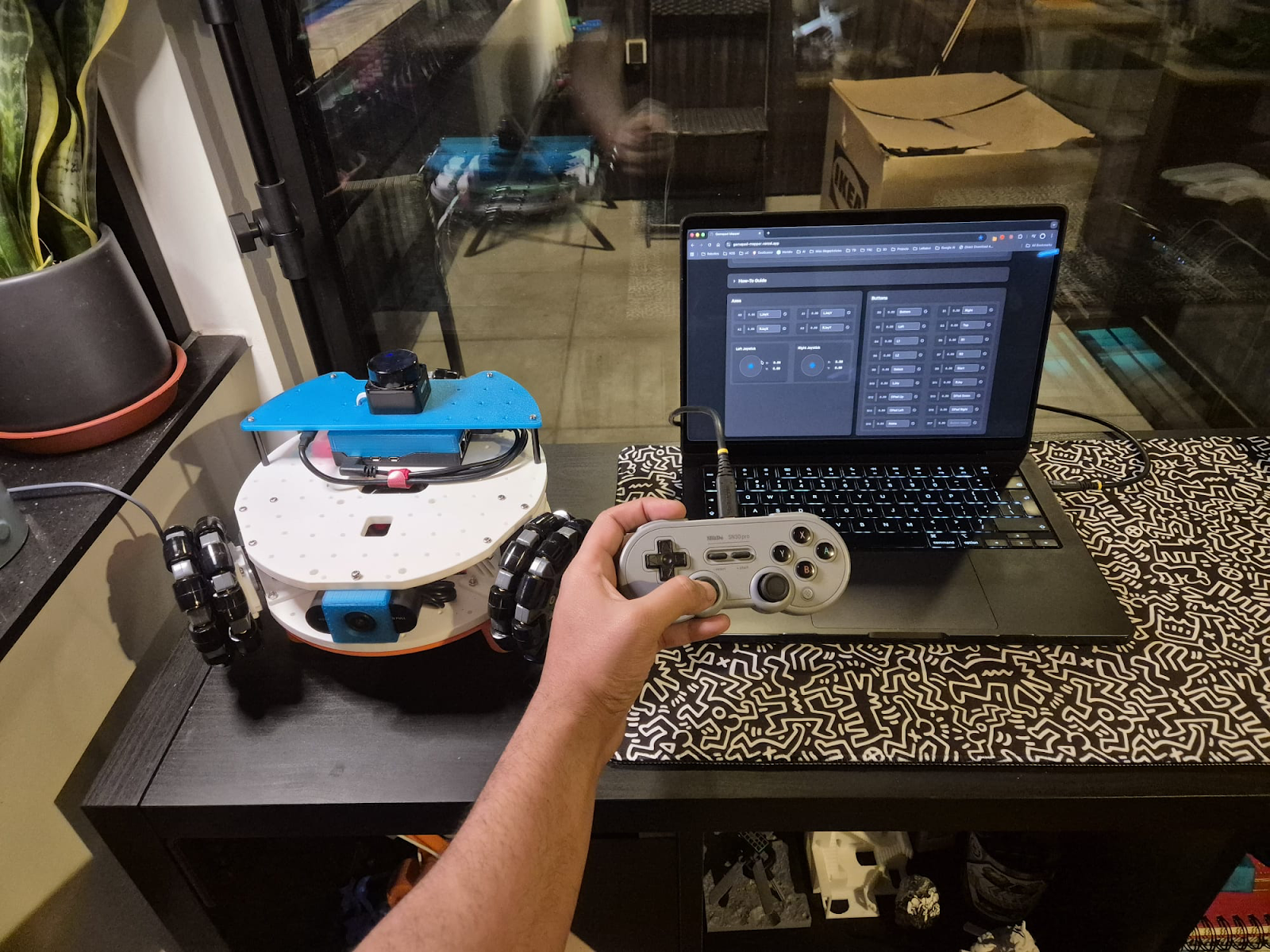
For the joystick inputs, I used the standard joy package to read data from a game controller and format it into a Joy message. I wanted to control the robot from my laptop, so I connected my game controller to it and ran the joy node there.
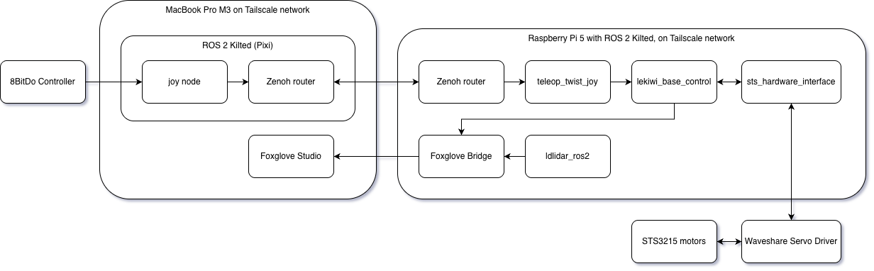
ros2 run joy joy_nodeFor communication between my laptop and the Raspberry Pi, I was already using Tailscale and decided to work with ROS 2 Kilted and Zenoh RMW as the middleware. However, this can be done in several different ways. For example, you could connect both devices to the same Wi-Fi network and use the different configurations provided by DDS alternatives like FastDDS or CycloneDDS. The integrated system looks like this:
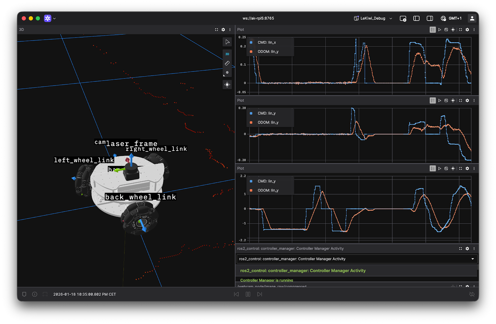
Finally, I fired up the Foxglove Bridge and used the Foxglove app to visualize the robot in action as I navigated it with my controller:
In the Foxglove app, I used the Plot panels to compare the measured velocities from the Odometry messages with the command velocities from the teleop_twist_joy node. This helped me determine realistic limits for the twist commands. Plus, the Diagnostics panels were really handy for keeping tabs on the ros2_control diagnostics data. I’m definitely using these tools for fine-tuning the robot’s odometry (which is surprisingly accurate right out of the box, just a bit noisy) and for my adventures with Nav2.
Summary
With the addition of a LiDAR and the ros2_control implementation tested using a game controller, I’m well on my way to modifying LeKiwi into a ROS 2-powered autonomous mobile robot. Foxglove has been an invaluable tool throughout this journey, from creating the URDF to fine-tuning teleoperation and testing the integrated system, and all on a MacBook (which famously has limited support for native ROS 2 installations). While the foundation for this project seems solid, there’s still work to do before moving on to autonomy.
For starters, the ros2_control configuration works with the default settings, but it needs to be fine-tuned. This includes odometry, which has been surprisingly accurate, but it is too noisy and could benefit from a filter. I also want to calibrate the camera and work with ROS 2 camera packages.
I am sure Foxglove will remain a key utility in what’s to come. Looking ahead, I’m excited to see this robot navigate autonomously, even though I don’t have a specific application for it. But I am certainly learning a lot during this journey and can’t wait to see where it leads!