Simulating Robotic Scenarios with ROS 1 and Gazebo
Visualize simulated sensor data with Foxglove
Simulation plays a crucial role in robotics development by allowing developers to assess their algorithms and designs without physical prototypes. In this tutorial, we will demonstrate how to simulate a robotic arm with physics-based simulator Gazebo and visualize it with Foxglove.
Setting up
Before getting started, install ROS 1 Noetic and Gazebo.
This tutorial assumes basic knowledge of ROS – the tutorials on the ROS Wiki and the Foxglove blog are a good place to brush up on your ROS basics.
Running the simulation demo
Before running the simulation demo, we must first build the simulation package in the foxglove/tutorials GitHub repo. See the README.md file for detailed instructions.
Once the package has been built and the workspace sourced, run the simulation:
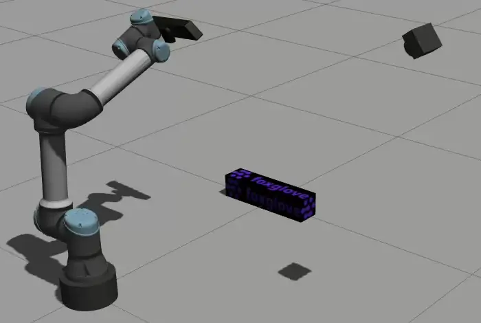
$ roslaunch fg_gazebo_example simulation.launchThis will start Gazebo and spawn a Universal Robot UR5e with a mounted depth camera, a fixed RGB camera, and a box-shaped object in the Gazebo world.To spawn a robot and camera models, you can provide URDF files that contain <gazebo> tags. These tags instruct Gazebo to create depth and RGB camera sensors and expose them on ROS topics using gazebo_ros_pkgs plugins.
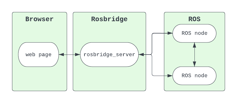
Besides the Gazebo simulation, simulation.launch also launches MoveIt to plan and execute robot motions. The simulation also launches foxglove_bridge to visualize the robot model and camera images in Foxglove.
Moving the robot
Run the Python script in the simulation demo package to execute robot motions using MoveIt’s Python API:
$ rosrun fg_gazebo_example move_viewpoints.pyThis will cause the robot to move through several positions to inspect the box with its mounted depth camera.
Use rqt_joint_trajectory_controller or MoveIt’s motion planning RViz plugin to move the robot to other arbitrary positions.
Visualizing with Foxglove
To visualize this data, download the latest version of the Foxglove desktop app.
Make sure that the ROS_PACKAGE_PATH setting includes your workspace, so that Foxglove can locate the mesh files referenced in the robot’s URDF file.
Next, open a live Foxglove Websocket connection – specify ws://localhost:8765 as the connection URL.
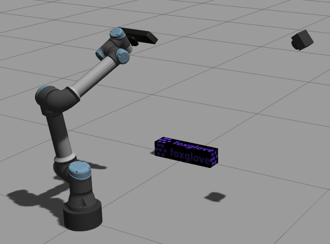
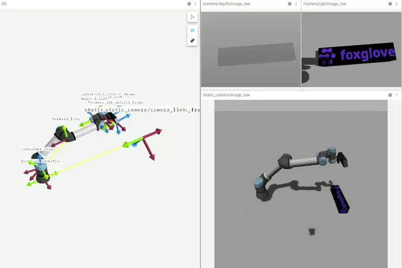
Add a 3D panel to visualize the robot model and all transforms. Then, add a few Image panels to view the RGB and depth image topics.
You should now see both the robot model and camera images visualized in your Foxglove layout:
Stay in touch
To reference all code covered in this post, check out our foxglove/tutorials GitHub repo.
As always, feel free to reach out to us directly in our Discord community to ask questions or request a topic for the next tutorial.