Introducing 3D Maps in Foxglove
See your robot data in the context of the world around it.
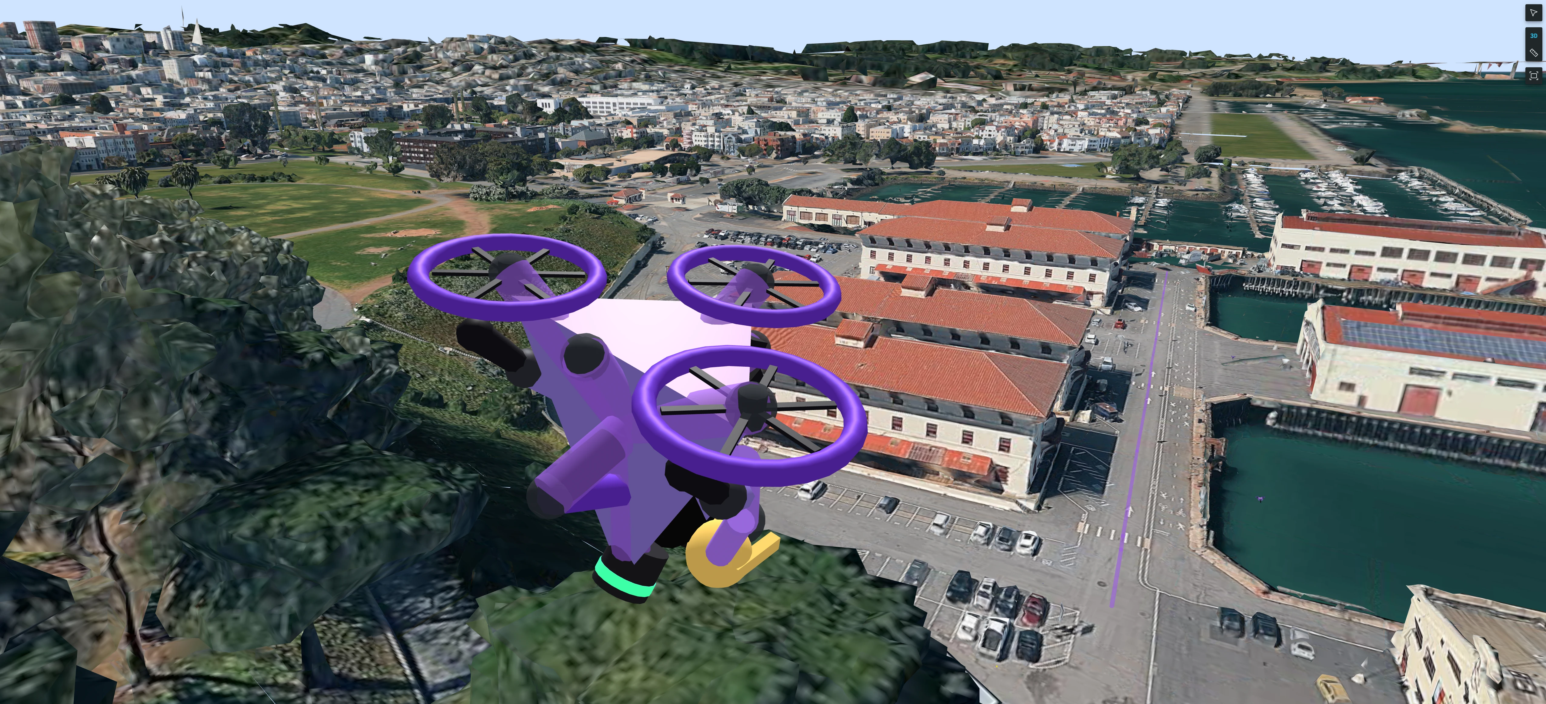

A robot’s path can tell you where it traveled, but understanding that path often means looking at what surrounds it. Was that turn beside a building? Did the route follow a hillside? When reviewing an outdoor run, having the environment in view helps you connect what your robot recorded with where it happened.
With 3D Maps, you can now add a photorealistic background to Foxglove’s 3D panel and view your robot data alongside the surrounding buildings and terrain. The feature currently uses Google’s Photorealistic 3D Tiles, anchored to your scene through a geographic location fix and your robot’s coordinate frames.
Our existing maps in the 3D panel place street or satellite imagery beneath your scene. 3D Maps adds the shape of the surrounding environment, making it easier to relate a trajectory or point cloud to nearby buildings and terrain as you move around the view.
See delivery drones in their surroundings
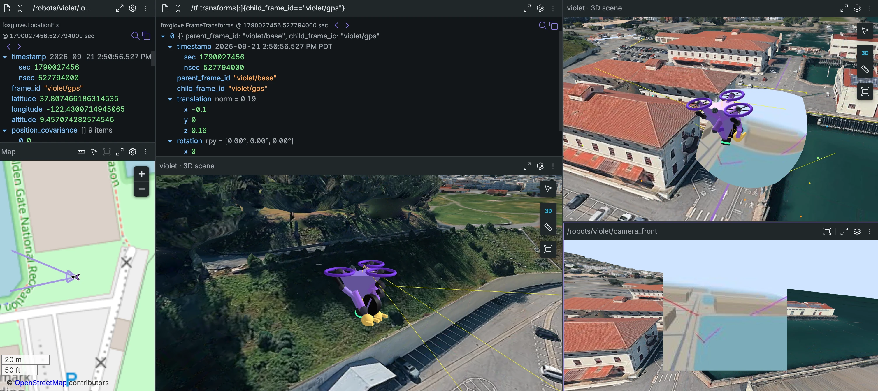
In the video below, simulated delivery drones fly over Fort Mason in San Francisco. Each drone publishes GPS, 3D transforms, LiDAR, camera feeds, and 3D scene annotations from onboard perception. With 3D Maps, you can view those signals together in one 3D panel against nearby buildings and terrain.
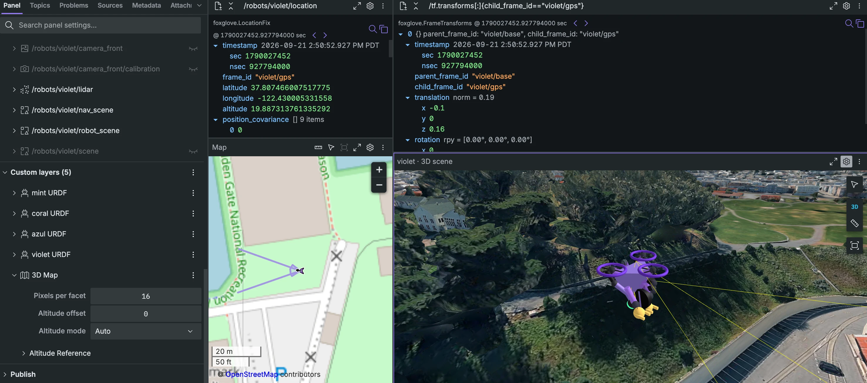
The screenshot below shows the drone’s location fix and the transform from violet/base to violet/gps, alongside 3D views and a camera feed. The GPS frame connects the drone’s geographic position to its position in the 3D scene.
Add a 3D Map
A location fix links latitude and longitude on Earth to a coordinate frame in your 3D scene. To align the map with your data, you need:
- A location topic containing geographic coordinates, such as
foxglove.LocationFixor ROSsensor_msgs/NavSatFix. - A frame linking that location to your 3D scene, specified by the message’s
frame_id(header.frame_idfor ROS). If the frame ID is missing or not in your transform tree, select the topic’s<Display frame>option under Frame → Location topic to anchor the location fix to the panel’s display frame.
We recommend setting frame_id to the GPS receiver’s frame so the transform tree accounts for its offset from the robot. See the LocationFix schema for the message fields. You can optionally configure an East-North-Up (ENU) frame to orient the 3D scene geographically.
- Open your data in Foxglove and add a 3D panel.
- Set Location topic (and optionally ENU frame) under Frame.
- Add a 3D Map from Custom layers.
- Resolve any layer warnings, then tune Altitude mode if needed.
The screenshot below shows the 3D Map layer under Custom layers, with Altitude mode set to Auto and Altitude offset available for adjustment.
Choose how altitude is aligned
The 3D Map layer’s Altitude mode determines how Foxglove aligns the map vertically with your scene:
- Auto (default): Uses the location fix’s altitude when it is provided, finite, and non-zero. Otherwise, it samples elevation from the 3D map to adjust the altitude.
- Location’s Altitude: Uses the altitude from your location fix. The panel warns if that altitude is missing or zero.
- Map Sampling: Always uses elevation sampled from the 3D map, even when your location fix includes an altitude. This is useful when your location data’s altitude is unavailable or unsuitable for alignment.
- Fixed Reference: Uses a fixed altitude that you can edit under Altitude Reference. You can also re-sample the map elevation at the current location fix to set that reference.
Location fix altitude must be in meters above the WGS 84 ellipsoid. Altitude measured above sea level uses a different reference and can leave the map vertically misaligned. Auto does not verify that reference or the altitude’s accuracy.
In the video below, a driving robot’s recorded altitude differs from the terrain in Google’s Photorealistic 3D Tiles. Auto uses that recorded altitude; selecting Map Sampling aligns the robot with the map surface. The GPS receiver sits on top of the robot, above ground level, so a small fixed Altitude offset brings the robot closer to the road surface for a more representative view of its driving conditions.
Coverage and loading
3D Maps depends on Google’s Photorealistic 3D Tiles coverage, so some areas may have less detail or no photorealistic 3D coverage. An internet connection is needed to download tiles, even when reviewing a local recording. Tiles load as you navigate the scene, so allow time for additional detail to appear when moving to a new area or zooming in.
Try 3D Maps
3D Maps is available on Pro, Academic, and Enterprise plans and currently uses Google’s Photorealistic 3D Tiles. Open an outdoor dataset with a location fix, add a 3D Map from Custom layers, and see the 3D panel docs for the full reference.
Need to visualize your own 3D map data or use a different map provider? Tell us about your workflow.