When working with large outdoor robots, I often needed two different views of the same system. One was the robot’s internal world: TF, URDF, odometry, paths, and navigation topics. The other was the real world: geographic position, terrain, roads, buildings, and the wider environment around the robot.
Existing tools covered parts of this workflow well, but I wanted both perspectives in one place. RViz was useful for robot-centered data, and Mapviz was great for GPS-based visualization, but I kept constantly switching between different views depending on the task. What I wanted was a single tool that could show the robot in a real-world 3D environment while keeping the ROS 2 data and navigation workflow connected.
To solve this, I built a Foxglove extension that renders photorealistic 3D tiles, overlays ROS 2 robot data, and allows interactive waypoint placement directly in the scene. The result is a much more practical way to monitor and plan navigation tasks in outdoor environments.
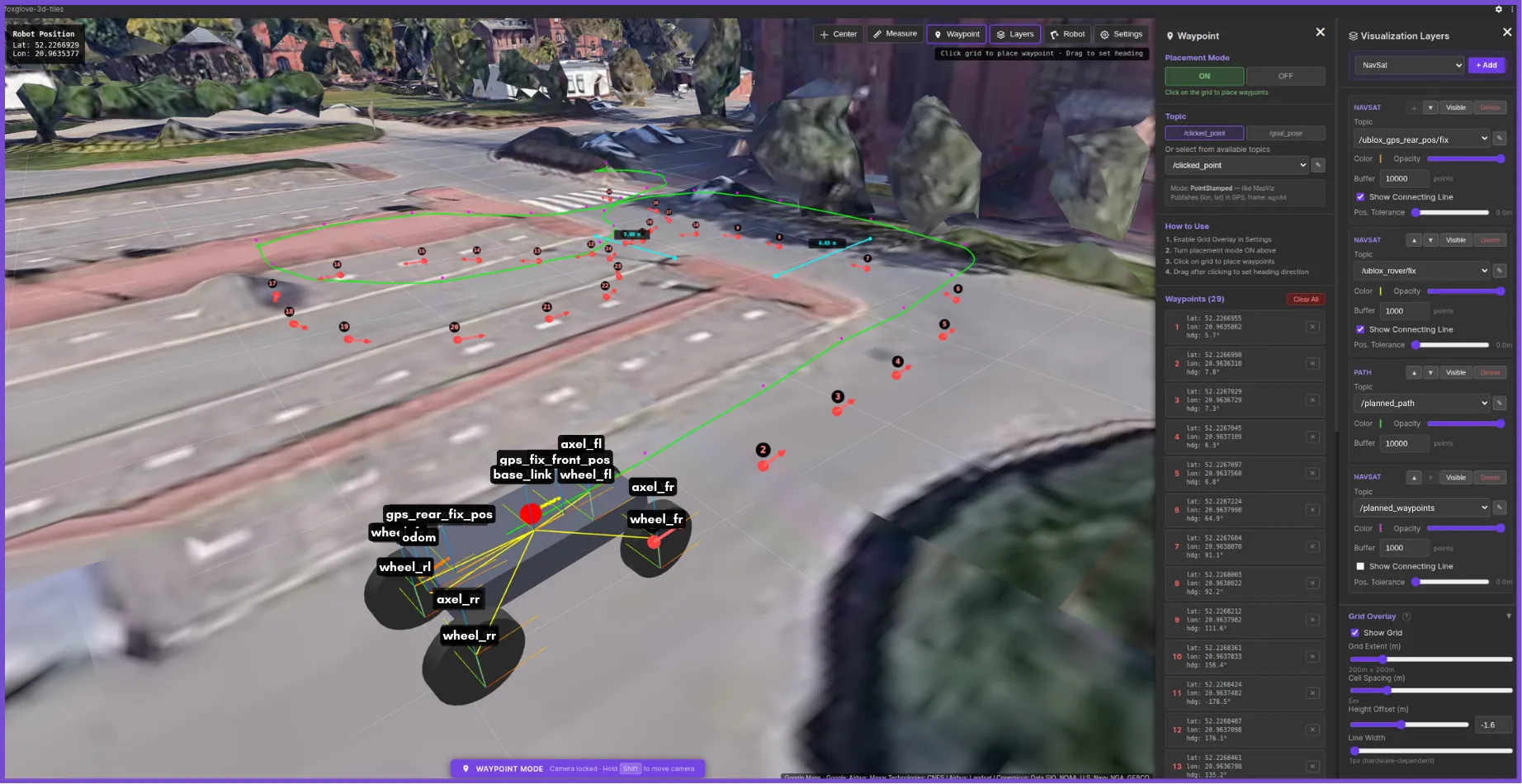
Live TF frames and navigation paths overlaid on 3D tiles.
Why Foxglove?
I wanted to extend my existing workflow rather than build another standalone tool. Foxglove already provides a strong ecosystem for robotics debugging, making it the perfect platform to build a specialized tool for outdoor navigation. By building this as a custom panel, map interaction, robot visualization, and topic monitoring can all occur side by side. The goal wasn’t just to visualize the robot in the real world, but to actively interact with it by placing waypoints, defining headings, and publishing goals without ever leaving the workspace.
Core capabilities: fusing the robot with the real world
The extension is built around three main ideas. First, it uses Google Photorealistic 3D Tiles or local 3D tilesets as the scene foundation, giving the robot a realistic outdoor environment instead of a flat or abstract map. Second, it overlays ROS 2 data, such as URDF, TF, GPS, odometry, paths, markers, and costmaps, directly into that same world. Third, it supports interactive waypoint publishing, allowing users to define navigation goals and headings without leaving the 3D environment.
Behind the scenes, the extension also has to connect local robot frames, such as map, odom, and base_link, with global geographic coordinates. This is handled through a local ENU anchor, which keeps the robot overlays stable while the globe remains positioned in global space.
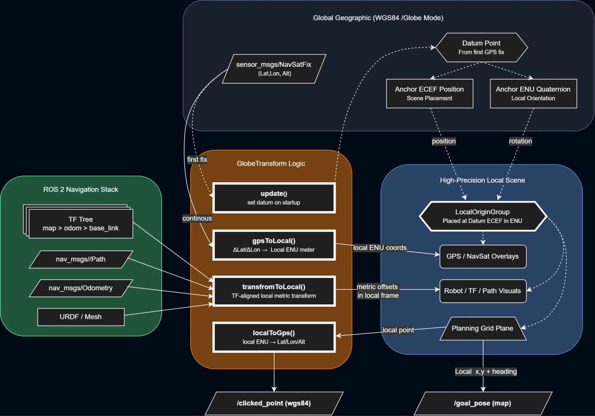
From global WGS84 coordinates to a stable local ENU frame used for rendering and interaction.
Solving the jitter problem
Once I had the 3D tiles rendering and the robot overlaid on top of them, I ran into a very annoying problem: the robot model and ROS trajectories were visibly jittering. Instead of moving smoothly through the scene, the model seemed to shake and snap every time the robot moved. It looked like a small rendering issue at first, but it took me a while to figure out what was actually causing it.
The root of the problem was the coordinate scale. In a global 3D environment, positions are often represented in Earth-Centered, Earth-Fixed (ECEF) coordinates, where values are on the order of millions of meters because they are measured relative to the centre of the Earth. That is fine for placing a globe, but it becomes a problem when you also want to render a robot moving by just a few centimetres or meters.
WebGL rendering uses 32-bit floating-point values, which provide limited precision for very large numbers. At the Earth scale, there is insufficient precision to reliably represent small robot movements. Those small changes get quantized, making the rendered geometry appear to jitter rather than move smoothly.
To solve this, I built a GlobeTransformer that pins a local GPS anchor and defines a local ENU (East-North-Up) frame around it. The globe itself stays at its real ECEF position, but the ROS data is transformed into small local coordinates relative to that anchor. In the scene, this is handled through a parent localOriginGroup positioned at the anchor and rotated into the ENU frame.
This means the robot model, TF data, paths, and other overlays are rendered using small local values instead of huge global ones. The result is a much more stable visualization and properly aligned overlays, even though the underlying map is still globe-scale.
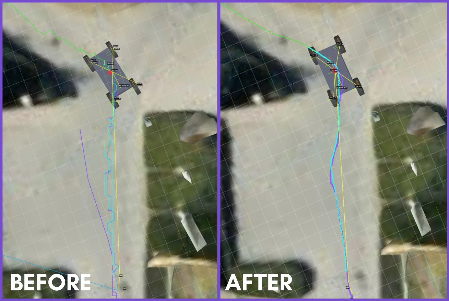
Rendering directly at Earth scale causes Float32 precision loss; anchoring the scene to a local origin keeps robot motion and overlays stable.
Interactive waypoints: publishing goals from the scene
One of the main reasons I built this extension was that I did not want it to stop at visualization. I wanted to interact with the scene and turn that interaction into actual ROS messages for use in a navigation workflow.
The panel supports two publishing modes. The first is a PoseStamped mode, intended for topics such as /goal_pose, where the result is a full 2D navigation target in the map frame. The second is a PointStamped mode, intended for /clicked_point, where the result is published in the WGS84 frame using longitude, latitude, and altitude.
The interaction starts with a mouse click in the scene, but internally, the click is not projected onto the raw photorealistic tile geometry. Instead, it is raycast onto a local planning plane aligned with the extension’s local coordinate frame. In practice, this functions like an interactive grid within the robot’s working area. That local point then becomes the source for publishing.
For /goal_pose, the local point is used directly as a navigation target in the map frame. The published message is a geometry_msgs/msg/PoseStamped with the selected x and y position, while orientation is generated from the chosen heading and converted into a quaternion. This makes the behaviour similar to a 2D navigation goal workflow, but inside a geospatial 3D scene.
For /clicked_point, the same local point is converted back into geographic coordinates relative to the anchored local frame. The extension converts back to GPS coordinates using the local ENU anchor offset, then publishes the result as a geometry_msgs/msg/PointStamped in the WGS84 frame. In that mode, the point is not just a visual marker. It becomes a real geographic output that other ROS tools can consume.
Heading selection is also part of the interaction. After placing a point, the user can drag to define direction, and that heading is then used when publishing /goal_pose. If the user only clicks without dragging, the extension either falls back to a default heading or, when possible, automatically infers a direction from the previous waypoint. This matters because in real outdoor navigation workflows, the robot’s final orientation is often just as critical as the target location itself.
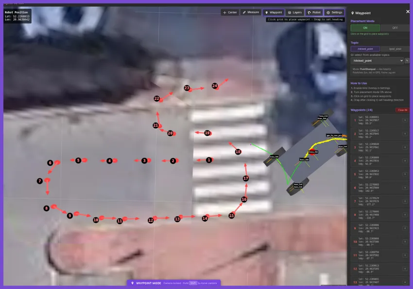
Interactive waypoint placement in the 3D scene, with support for publishing both /clicked_point and /goal_pose.
What works, and what still needs work
In practice, the core workflow of planning goals and monitoring navigation in a real-world 3D context is already useful. However, as an evolving project, there is still room to improve.
Support for local custom tilesets is functional but requires further refinement. Going forward, I want to improve the custom tile pipeline and add native support for richer overlays like LiDAR point clouds—a feature I am currently exploring as part of a university project. The main goal is to continue making the panel more robust for a wider range of outdoor robotics workflows.
About the author
Jion Kubo is a robotics developer currently interning at the Łukasiewicz - Poznań Institute of Technology while completing his degree in Automatic Control and Robotics at Poznan University of Technology. With a background spanning embedded engineering and control systems, he spends most of his time developing within the ROS 2 navigation stack. His other technical interests include SLAM and autonomous navigation.