Using Foxglove as an SO-101 Simulator
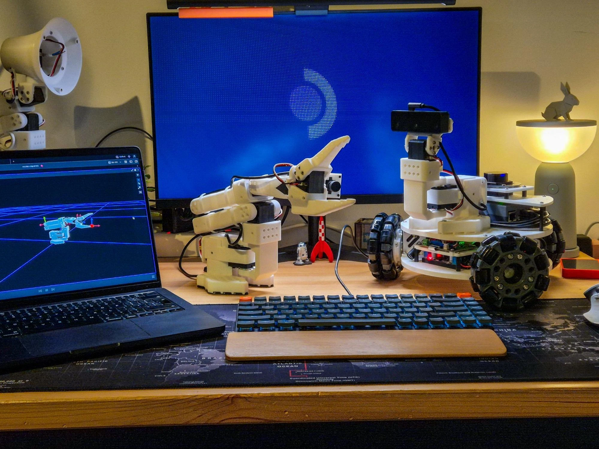

tl;dr While on a little hiatus from the LeKiwi robot, I decided to build a new SO-101 arm and, in parallel, decided to work on the software side first - using ROS 2 Control and sts_hardware_interface’s mock mode to fake the servos, and Foxglove’s 3D panel to see whether any of it worked. Over a couple of weekends, I built an inverse kinematics-driven teleoperation node, a manual joint-control fallback, and self-collision checking. I watched each feature work as expected on a simulated arm on the Foxglove app before the real one was fully assembled or calibrated.
Project Context
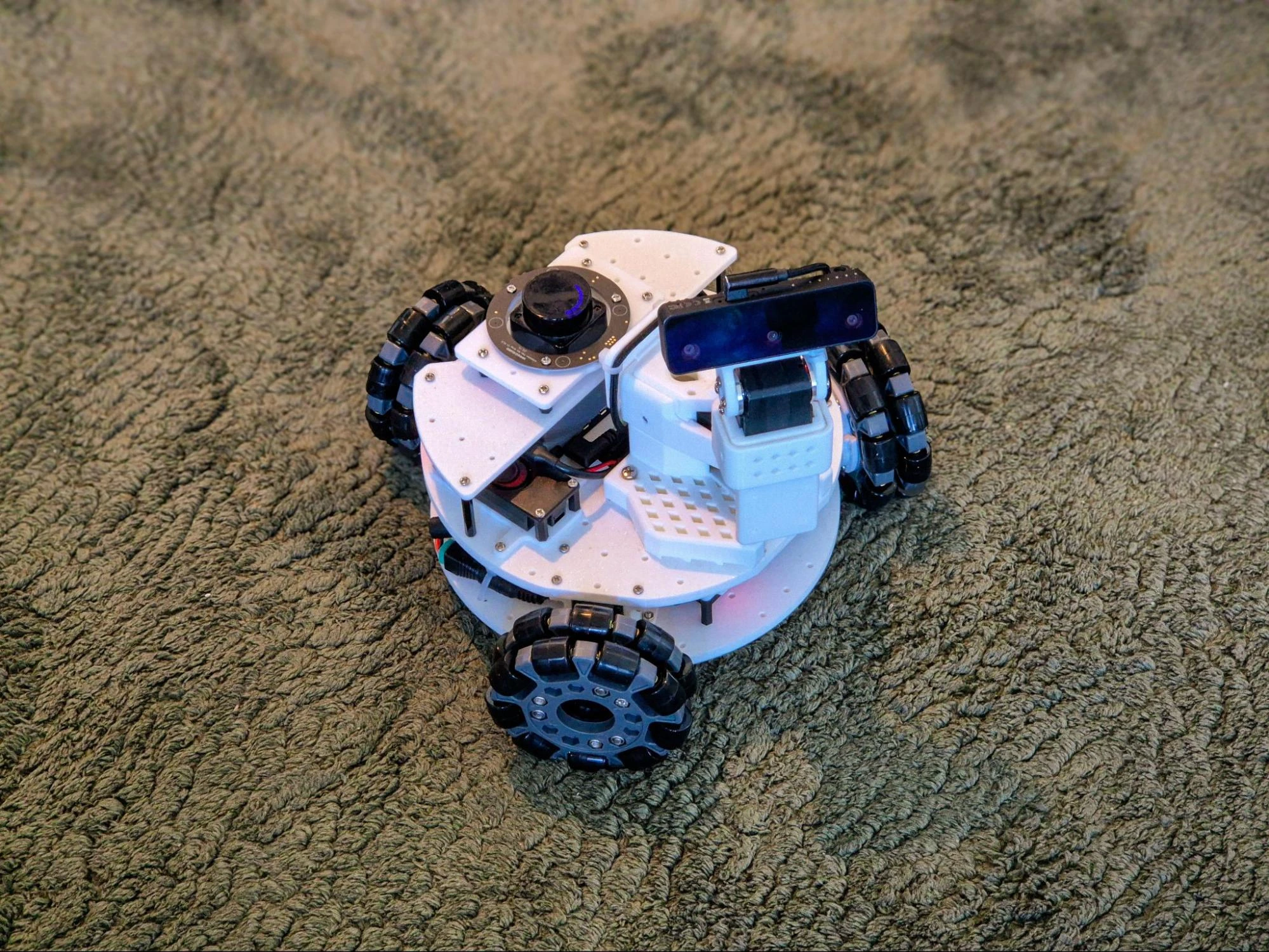
This post is part of a new series about building a ROS 2 stack for the SO-101, an open-source 5-DoF robot arm - much like I’ve been doing all year for LeKiwi, a holonomic robot that uses the same STS3215 motors from Feetech. The SO-101 arm, just like LeKiwi, is normally operated using LeRobot, Hugging Face’s framework for embodied AI, but I’m using ROS 2 instead, on top of sts_hardware_interface, the same ros2_control hardware interface that already drives LeKiwi’s base.
Before I continue, a clarification on the title: I know Foxglove is a visualization and observability platform, not a simulator, and I know the title raises an eyebrow. But alongside the hardware interface, it ended up doing a simulator’s job for me - providing the crucial visual feedback that told me whether the software was working before there was any hardware to check it against.
Mock Mode
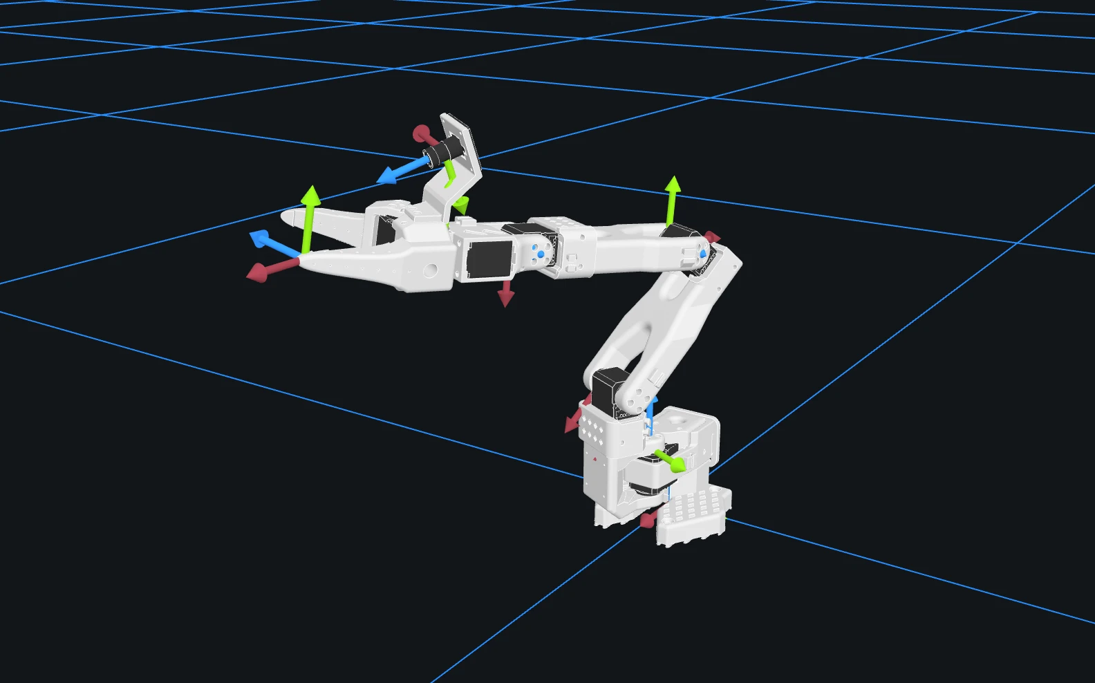
Since assembling/calibrating the physical arm took time, I started working on the software stack in parallel, focusing on the controller configuration and a teleop scheme. Thanks to sts_hardware_interface’s mock mode and the SO-101 URDF, I could mock the entire arm in software and didn’t have to wait for the real hardware to be ready. In practice, I simply set the mock mode flag in the hardware interface configuration to true, telling the hardware interface to fake the servos’ feedback internally, while the rest of the ROS 2 stack has no idea it isn’t talking to real motors.
This works because of how ros2_control is structured: everything above the hardware interface - controllers, trajectory planners, collision checks - only talks to a standard set of command and state interfaces. The hardware interface translates commands into whatever data the actual hardware needs and publishes the state interface values that it reads from the hardware. Swap the real hardware with a simulated one, and the other elements in the ros2_control structure cannot tell the difference.
When the mock mode is enabled, instead of writing to a real servo bus, sts_hardware_interface fakes both sides of the interface - not just the commands, but the state feedback too. And it doesn’t just echo back whatever you send it; it behaves as a real servo would - the voltage drops under load, temperature climbs with activity, and the current draw follows the commanded effort. In both real and mock cases, the emergency stop service does what it says, but the real motors are affected by gravity, and the arm naturally droops down. In mock mode, the joint motors stay in the same position.
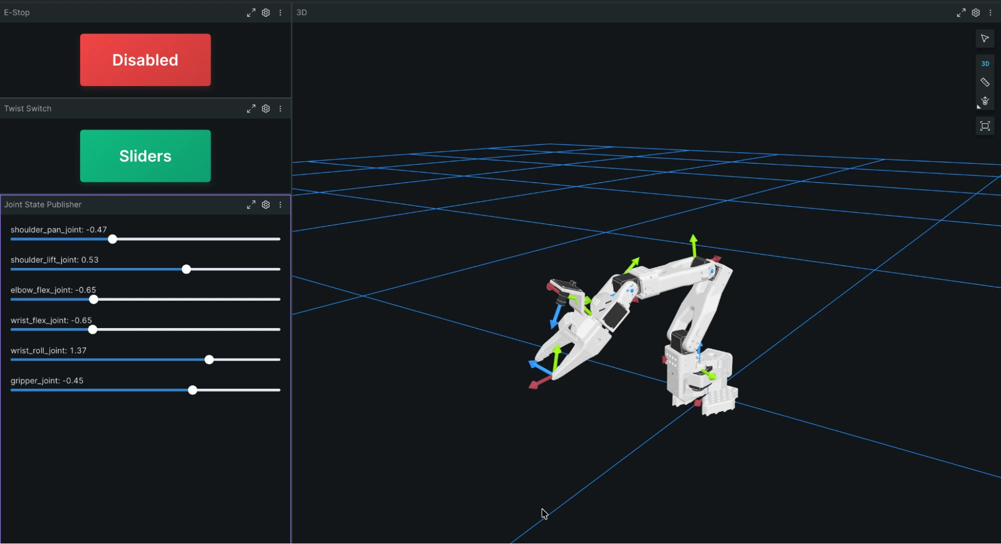
Aside from external forces like gravity and collisions with obstacles, mock mode is sufficient to design and test high-level behavior. This meant that I could start building the software stack on my robot against the simulated arm, without needing to plug anything in.
Teleop with Inverse Kinematics
The first real feature I wanted was a natural way to move the arm: point at where I want the end effector to go, and let it figure out the joint angles by itself, rather than me driving the joints individually.
To do this, I first built a small virtual target that I could move around in 3D space - nothing exotic, just a simple coordinate frame that I could manipulate using joystick controls, which the end effector would then try to track. I also added a target_visualizer_node that publishes a colored marker at the target’s pose, so that I can visualize it from Foxglove’s 3D panel.
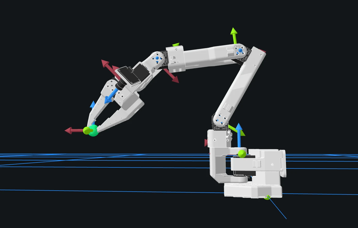
To track the target, I then added teleop_ik_node, which runs inverse kinematics (IK) using Pinocchio to continuously solve for joint positions that get the end effector to its target pose. I won’t go into the IK math here - the repo has all the code if you’re curious - but the experience of testing it is what stuck with me: I would nudge the joystick, watch the marker move, and the arm would chase it. Genuinely fun to work with, even in mock mode.
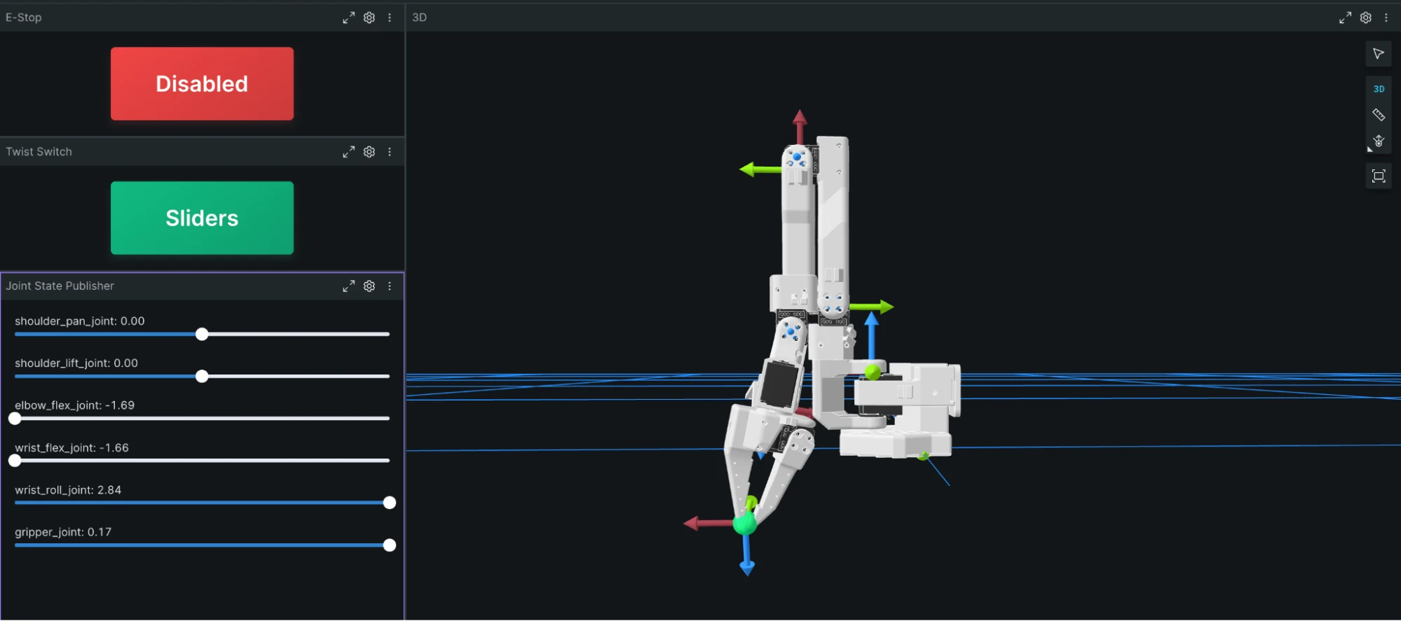
This IK-based teleop made controlling the arm much more intuitive, but I also wanted the ability to control the joint angles individually when needed, especially for debugging. For this, I used Joint State Publisher, a community-contributed Foxglove extension available in the extension registry. To prevent conflicts between the IK teleop commands and the manual joint commands, I implemented a switching mechanism in joint_state_switch_node that can toggle between the two commands using a single service call, which can be triggered from a joystick button (using joy_teleop), Foxglove’s Service Call panel, or my custom Button extension. It is incredibly satisfying to move the individual joints using the sliders, then switch to the teleop mode and watch the IK solver take over and move the joints to optimal positions, while maintaining the same target.
Self-Collision Checking
While testing teleoperation, I realized that the arm could easily be commanded into positions that would cause it to collide with itself. In simulation, this isn’t a big deal - the meshes simply pass through each other, but on a real robot, this would break something. So, the next step was to implement self-collision checking that would run on every joint command, regardless of its source.
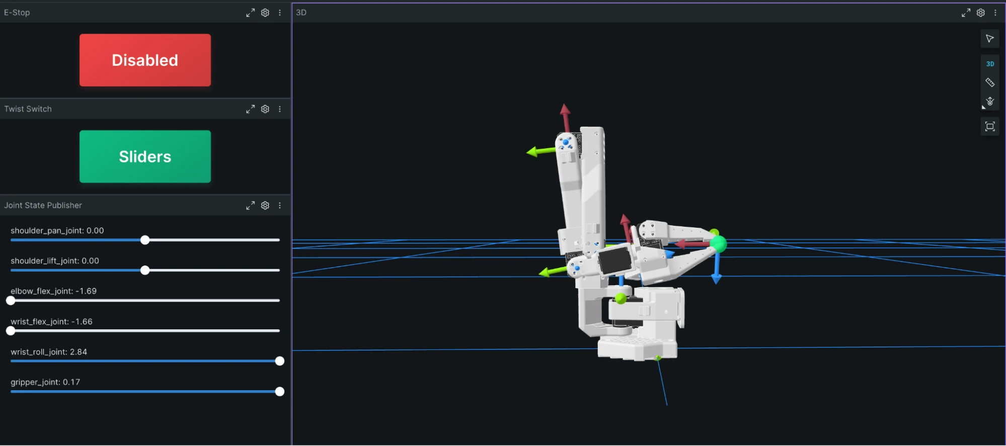
I used FCL, which checks the arm’s own geometry against itself using bounding volumes. It’s deliberately lightweight compared to using MoveIt, which wasn’t required at this stage - and it checks the whole path to a target, not just the destination, since two individually safe configurations can still cause a collision on the trajectory between them. Rather than just rejecting a colliding command outright, CollisionResolver first tries to clamp the target back to the last safe point along that path, and only rejects it if that fails. This can be seen in the image below.
The Agent Sidebar
A few weeks ago, the Foxglove team provided me with a year-long enterprise account along with early access to some of their newest features - and I’ve been dying to talk about it ever since. One of those features is the Agent Sidebar, a built-in AI agent that answers questions grounded in whatever data is actually loaded in the layout.
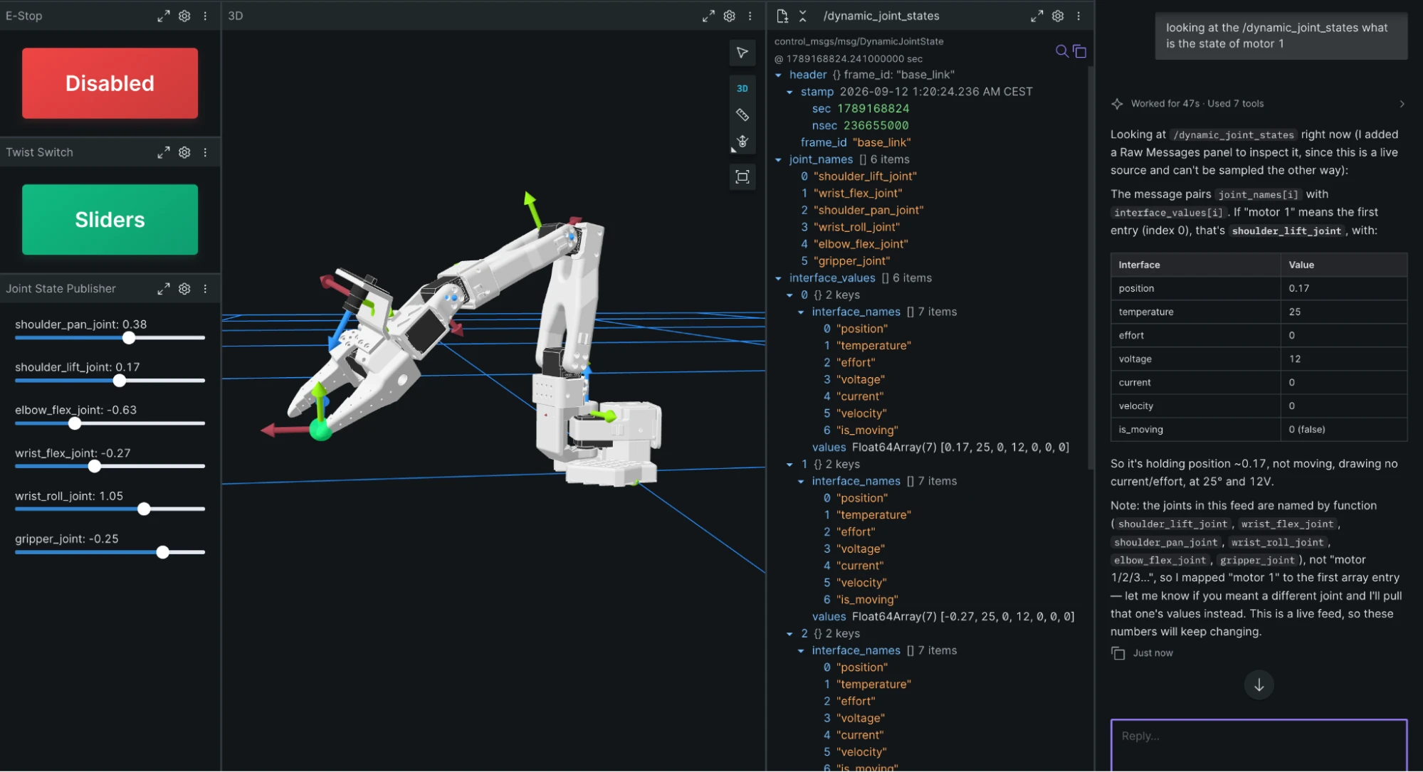
I used it mostly while debugging mock mode. Asking questions in plain English worked, but took a while to get an answer back; asking the same thing with an @ topic mention - pointing it straight at dynamic_joint_states, for example - was noticeably faster. Since the original layout did not show the dynamic_joint_states, it opened a raw message panel to capture the data.
One thing I liked was expanding the tool-call trace to see what it was actually doing behind the scenes, rather than just trusting the answer. I tried this on LeKiwi too, and it correctly figured out that LeKiwi doesn’t use the standard Twist message for velocity commands, but TwistStamped instead, and adjusted what it queried accordingly - a small thing, but exactly the kind of detail that’s easy to get wrong if you’re not actually looking at the data.
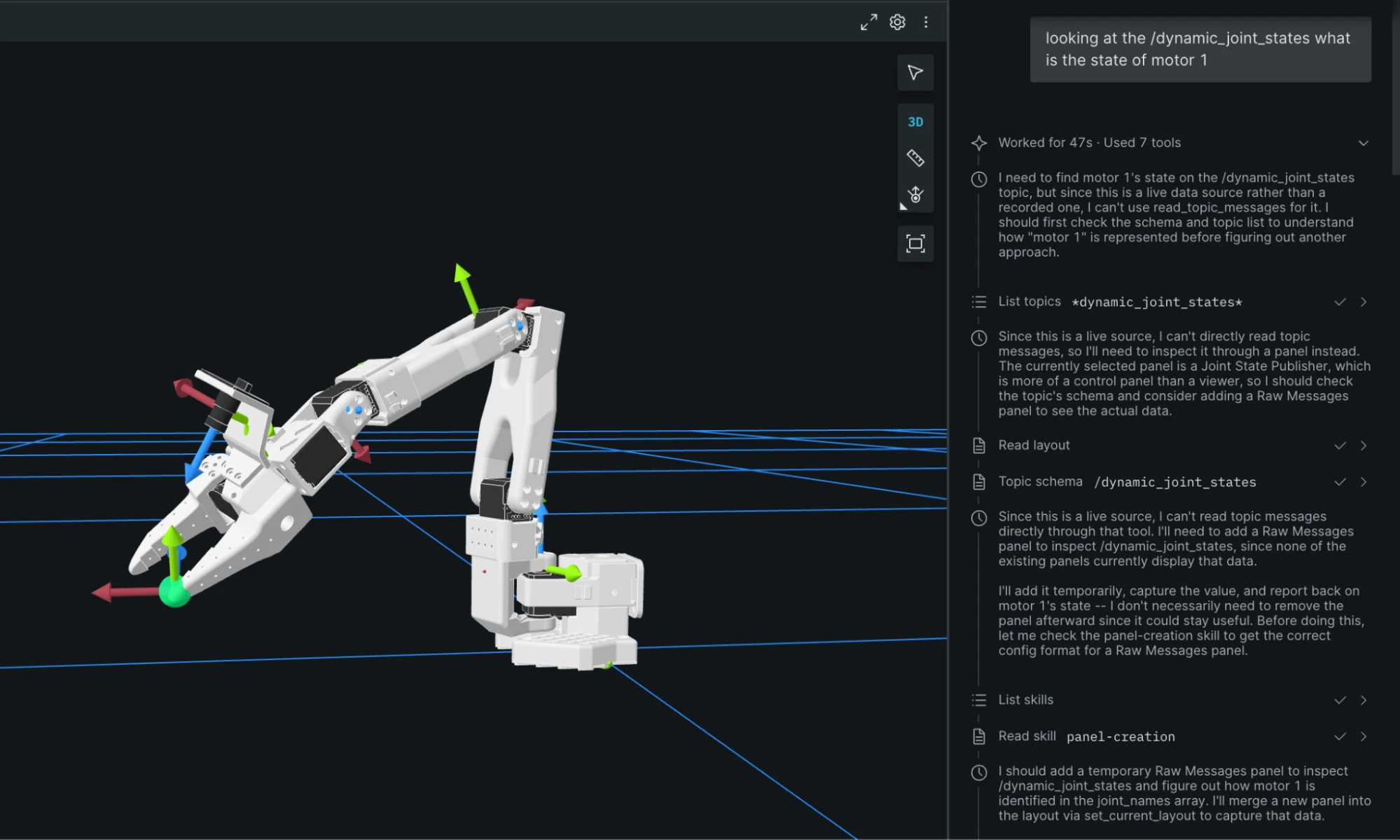
The Agent Sidebar can also be pointed at your own MCP-connected agent instead of the built-in one, which I haven’t tried yet - that’s going in a separate post where I get into the AI tools I actually use day-to-day.
What I liked most was using the agent sidebar to build layouts. I gave the agent a generic prompt - to improve my layout without removing any existing panels - and it provided a detailed layout with three tabs: one for monitoring, one for control, and one for diagnostics. It also worked cleanly with 3rd-party extensions, including the Button panel and the joint state publisher.
Turning Mock Mode Off
For the simulated arm, I used ROS 2 Kilted running on Pixi on my MacBook, which also brought up the Foxglove Bridge, letting me connect using the Foxglove app on the same device. Joystick inputs came from my Steam Deck, talking to the ROS 2 graph over Zenoh.
Once the real arm was ready and calibrated, I simply replaced use_mock:=true with serial_port:=... while running the launch file, and I was good to go. Of course, while useful, the simulation can never fully replicate the arm’s real-world dynamics, so I need to do some additional tuning. For a ROS 2 package tested on a mocked arm, performance on the real arm is not too bad.
What’s Next
During these couple of weeks, I learned just how valuable mock mode can be - if your hardware interface can fake its I/O convincingly, and you have a visualization platform like Foxglove that can render the result in real time, you don’t need working hardware to build against. But now that I have the real arm up and running, I want to start exploring its capabilities. The first thing I want to implement is a record-and-replay feature - capturing a sequence of movements of the arm as an MCAP file, and then replaying it back on demand. I’ve already started working on this, and there’s a rough version taking shape. Once it is done, it’ll be a blog post in its own right.
Since I’m thinking of recording MCAP files, I want to naturally try out Foxglove 3.0.0’s new features that they launched recently. I’m looking forward to tinkering with Comparison Mode to load several recordings onto one timeline and see how closely they line up and where they diverge. This would be useful for comparing mock mode with the real arm, or even for fine-tuning PID coefficients further.
Everything I talked about in this post - the mock mode internals, the IK solver, the collision resolver - is provided in so_arm_ros2 and sts_hardware_interface repositories. sts_hardware_interface is in a stable place, but so_arm_ros2 is a work in progress. If you find something worth fixing or building on, I’d love to hear about it.