
tl;dr This article details how I added autonomous navigation to my LeKiwi robot using Nav2, covering LiDAR filtering, mapping, and localization, and configuring Nav2 for a holonomic platform. I used Foxglove’s 3D panel throughout to watch the map grow during mapping, set the initial pose estimate for localization, and send navigation goals directly on the map. The result is a mobile base that navigates autonomously, with a seamless switch between teleop and Nav2 control.
Project Context
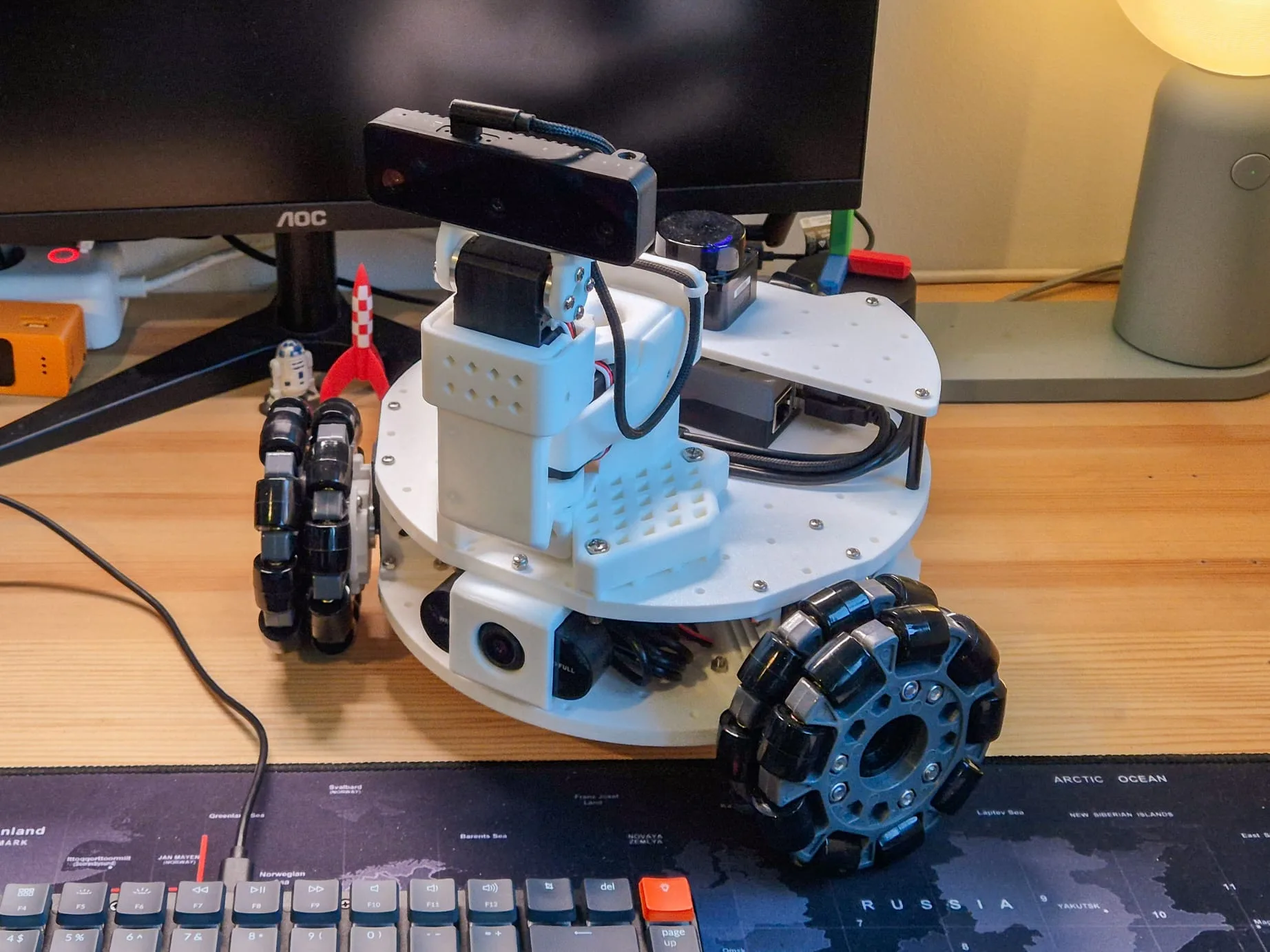
This is the next chapter in my ongoing series of building a ROS 2-powered autonomous mobile robot based on the LeKiwi platform. So far, I’ve integrated a LiDAR, calibrated the onboard camera, implemented teleoperation using a Steam Deck, and added a BNO055 IMU with sensor fusion for reliable odometry.
With the perception stack, teleoperation, and odometry in place, autonomous navigation was the obvious next step. This post covers how I got Nav2, a popular ROS 2 navigation library, running on LeKiwi, from the sensor prerequisites through to sending navigation goals in Foxglove.
The implementation lives in the lekiwi_navigation package in my lekiwi_ros2 repository.
Step 1: Setting Everything Up
For the basic Nav2 setup, you need a reliable odometry transform (odom → base_link) and a clean LiDAR scan. I could also have gone down the vision route and used the on-board cameras for visual-inertial odometry (VIO) or visual SLAM (vSLAM), but I chose to keep it simple for now.
Odometry and Sensor Fusion
The STS3215 motors used in the LeKiwi provide accurate state feedback (position and velocity), so the odometry from the omni_wheel_drive_controller is quite reliable. However, since I had already integrated the BNO055 IMU, I fused its measurements with the wheel odometry using the Extended Kalman Filter (EKF) node from robot_localization to get a more robust odometry estimate. This provides a stable odom → base_footprint transform that both Nav2 and slam_toolbox rely on. I’ve written a detailed article about the sensor fusion implementation on my own blog.
I’ve now got a working odometry source that runs at 50 Hz and publishes filtered/fused odometry messages on /odometry/filtered, along with the required odom → base_footprint transform (on my robot, base_footprint is the root frame of my platform, not base_link).
LiDAR Filtering
When I covered the LD19 hardware integration previously, the raw scan provided a 360° scan, but since then, I’ve added a pan-tilt camera mechanism that sits right in front of the LiDAR. Without filtering, part of the scan would show up as a permanent obstacle during mapping.
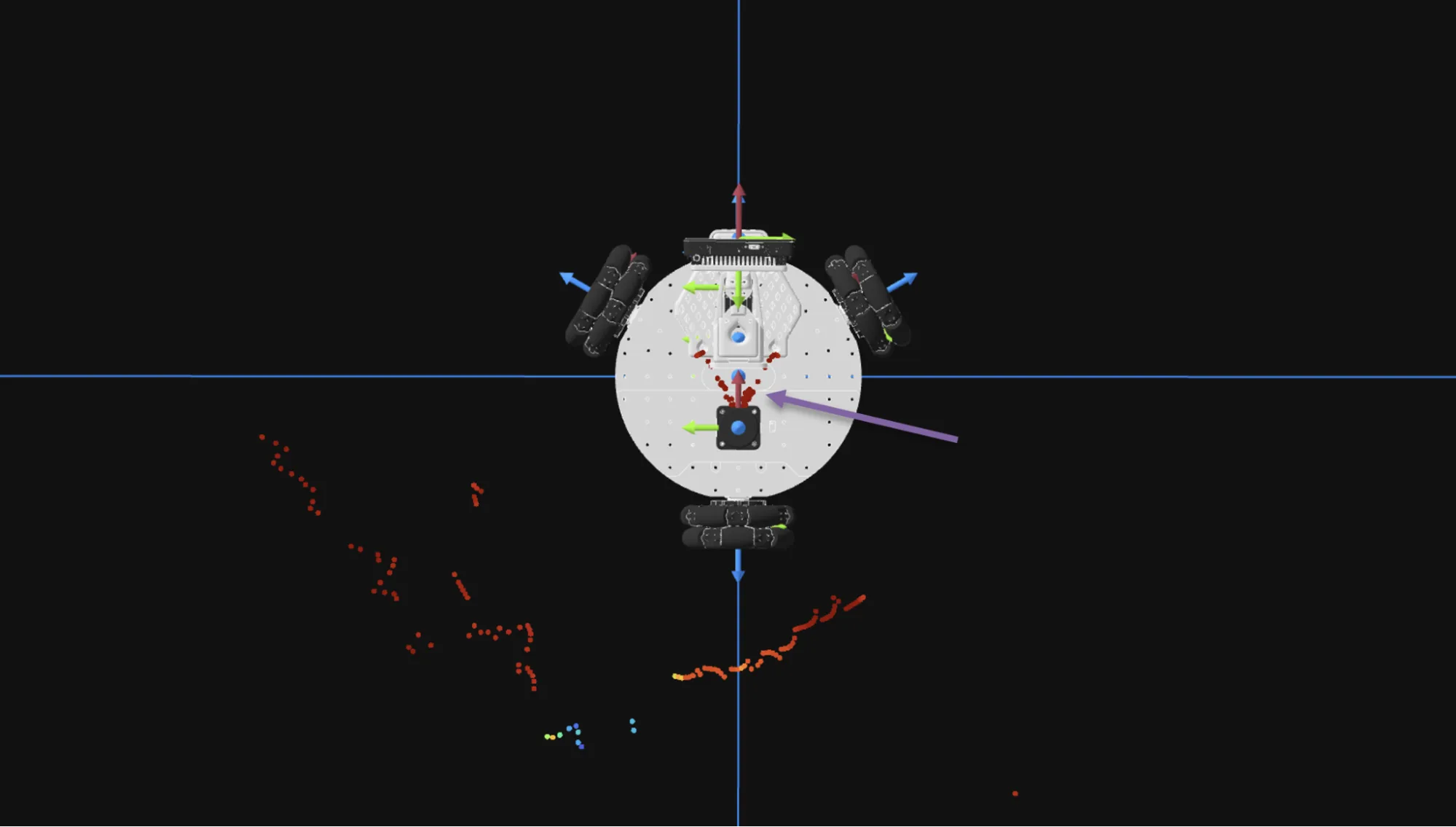
To fix this, I used laser_filters. The scan_to_scan_filter_chain node subscribes to the raw LiDAR output (now remapped to /scan_raw), applies an angular range filter that masks out the sector occupied by the pan-tilt mechanism (nearly 70°), and republishes on /scan. Everything downstream subscribes to this filtered scan topic.
# scan_filter.yaml (excerpt)
scan_filter_chain:
  - name: angle_filter
    type: laser_filters/LaserScanAngularBoundsFilterInPlace
    params:
      lower_angle: -0.6 # rad
      upper_angle: 0.6 # rad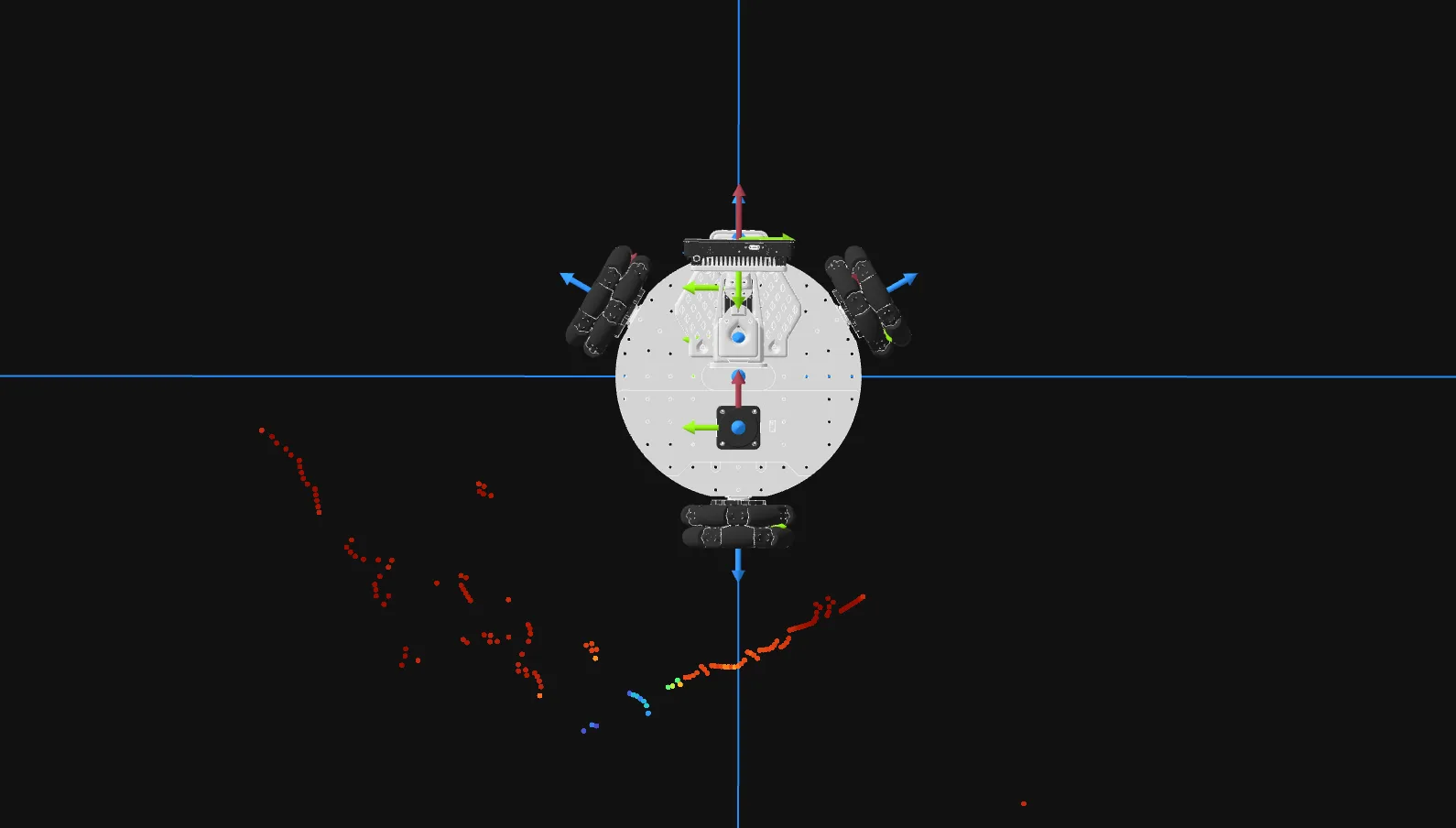
With the filter in place, the scan displayed in Foxglove’s 3D panel looks as expected: a clean scan around the robot, with the obstructed sector correctly filtered out.
Step 2: Creating the Map
With odometry and a clean scan in place, the next step was to build a map so that I could navigate in it.
Mapping using slam_toolbox
I used the recommended approach of using slam_toolbox in asynchronous mapping mode to build the map. This package implements Simultaneous Localization and Mapping (SLAM) using a pose graph approach and builds a map incrementally as the robot moves. The asynchronous mode lets it process scans as fast as possible without blocking the rest of the system, which matters on a Pi 5.
The main tuning I did was to reduce the scan processing rate (the LD19 runs at 10 Hz, which is more than slam_toolbox needs for a slow-moving indoor robot), cap the laser range to something sensible for indoor use (8 meters in my case), and push down the map rasterization frequency since that step is expensive and the default is unnecessarily aggressive. Nothing fancy, just bringing the defaults in line with the hardware.
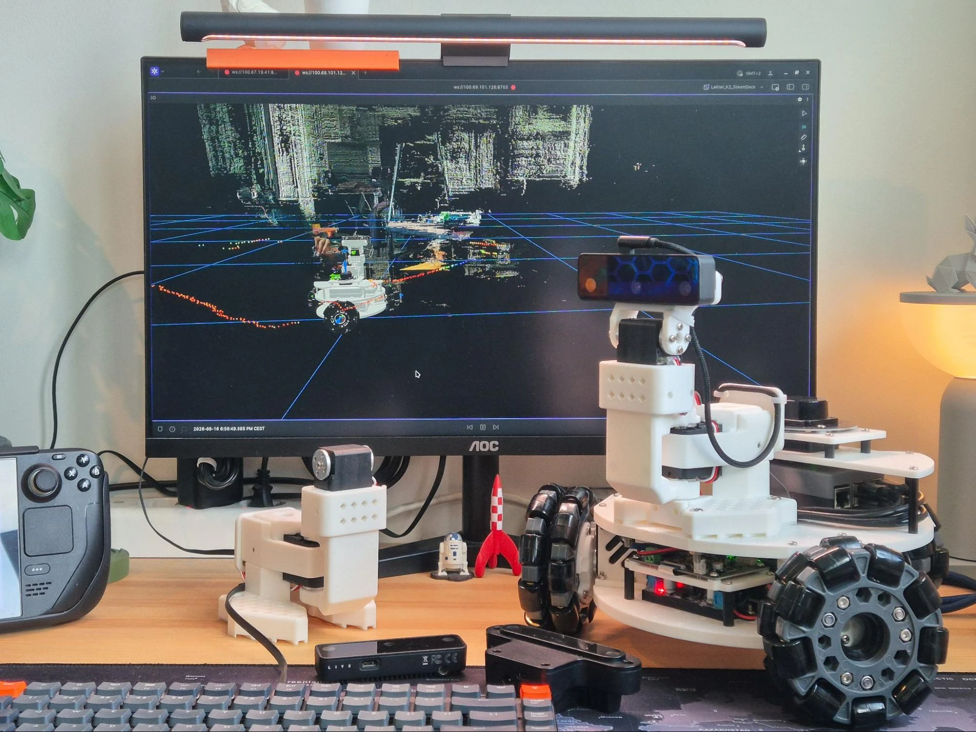
I then drove the robot around until the map looked complete in Foxglove’s 3D panel, watching it grow and close loops in real time.
Saving the Map
You could technically keep using mapping mode for navigation; slam_toolbox would localize and update the map simultaneously. The problem is that it starts from scratch every session, which is not ideal. So, in order to have a consistent map for navigation, I needed to save the map and use it with a dedicated localization method for autonomous navigation.
slam_toolbox lets you save maps using service calls, but this means that I need to interrupt my mapping session, switch to a terminal, and call the service every time I want to save a map. To make my life easier, I wrote a small map_saver_node script that listens to /joy messages and triggers the save when I press the R1 button on the controller. This way, I can save the map on the fly. When triggered, the node does two things in sequence:
- Calls
/slam_toolbox/save_mapservice, which writesmap.pgmandmap.yamlfor use with AMCL andnav2_map_server. - Calls
/slam_toolbox/serialize_mapservice, which writesmap.posegraphandmap.data, the binary formatslam_toolboxneeds for its own localization mode.
Step 3: Localizing in the Map
With the map saved, the next question is where the robot is within it. Nav2 needs a map → odom transform to plan and execute paths, which is the job of the localization layer. My original plan was to use slam_toolbox’s built-in localization mode, which can do this, but I also wanted to try AMCL for comparison, since I’ve been using it since ROS 1 and am more familiar with it. Eventually, I decided to keep both and use a launch argument to switch between them.
Option A: Localization using slam_toolbox
slam_toolbox offers a localization mode that reuses the serialized pose graph from the mapping step. It loads map.posegraph and map.data and runs scan matching against the stored structure, so it can handle loop closures and continuously refine the map as the robot moves. The robot starts from the map origin or from a known position configured at launch; either way, once scan matching locks in, it stays solid.
The catch is that the robot’s starting position needs to be somewhere recognizable in the saved map. On my setup, I just start the robot from the same spot every session, and localization snaps in immediately. While the localization is perfect, the map has changed; I’ve closed a door and added an obstacle. Despite this, the localization is never lost, and in addition, the map is eventually updated, which can then be saved again.
Option B: AMCL
AMCL (Adaptive Monte Carlo Localization) works from the static map.yaml loaded by nav2_map_server. It runs a particle filter and can converge from any starting position; you just need to give it an initial pose estimate. The map stays fixed (no loop closures, no incremental updates), but in return, you can start anywhere and re-initialize at any time.
For AMCL, I provide the initial pose estimate directly from Foxglove. The 3D panel lets you publish a 2D pose estimate by clicking on the map, which publishes a geometry_msgs/PoseWithCovarianceStamped on /initialpose, exactly what AMCL listens to. In the video above, I provide an approximate position estimate that is not too far away from the robot’s actual position. However, as I move the robot around, AMCL improves the position estimate. This can be seen from the covariance ellipse, which shows the uncertainty and reduces in size as the localization improves. One downside of AMCL is that it does not update the map, even though some minor changes are clearly visible. Despite this, the localization is still quite precise. However, if the environment changes drastically, I would not recommend AMCL unless a new map is created first.
Switching between modes
Now, I have three separate operating modes: slam_toolbox mapping, slam_toolbox localization, and AMCL. I implemented all three in a single slam.launch.py with a slam_mode launch argument for switching between modes, which is set in the top-level bringup launch file and passed down. Here’s how to use it:
# Mapping with slam_toolbox
ros2 launch lekiwi_navigation navigation.launch.py slam_mode:=map

# Localization with slam_toolbox
ros2 launch lekiwi_navigation navigation.launch.py slam_mode:=localize map_name:=studio

# Localization with AMCL
ros2 launch lekiwi_navigation navigation.launch.py slam_mode:=amcl map_name:=studio
Note that the map_name argument specifies which map to load for localization - it corresponds to the name of the folder created by the map_saver_node script, which contains all the necessary files for both localization modes.
Step 4: Navigating the Map
Now that I have everything in place - reliable odometry, a clean scan, a map, and the ability to localize in it - the last step is configuring Nav2 itself.
Nav2 Configuration
I wanted to get the basic configuration up and running, so I started with navigation_launch.py from nav2_bringup as a reference, and then stripped down the example configuration to use only what I needed. I put this in a custom nav2.yaml.
Nav2 is not a monolithic stack; it’s a set of separate nodes orchestrated by bt_navigator. When a goal arrives, bt_navigator runs a Behavior Tree: it asks planner_server for a global path, hands it to controller_server to follow it, and calls behavior_server if the robot gets stuck. I used the default Behavior Tree config, which is all you need for a simple point-to-point navigation project.
Since LeKiwi is holonomic, I went with MPPI as the controller choice with motion_model: Omni. For the planner, I went with SMAC 2D: A* on the costmap grid with no kinematic constraints, which suits a holonomic robot well. One thing to watch: velocity limits need to match the hardware and be set consistently across all Nav2 components, or MPPI will plan trajectories that the controller will reject. Once again, my goal was to get a simple configuration working first, so I did not dig into the advanced configuration options. My full configuration can be found here.
To send navigation goals, I used Foxglove’s 3D panel, which has a built-in nav goal publisher (I had to change the topic name to /goal_pose). I click a point on the map, drag to set the heading, and the robot starts navigating. Watching the costmap update, the planned path appear, and the robot follow it in real time in the same panel is what makes Foxglove particularly satisfying for this kind of work.
In the video above, I also show how to run the navigation stack in mapping mode. While it is fun to play with and quite useful for mapping unknown spaces without teleoperation, I would not choose this method over navigating on a pre-made map. The map provides crucial information about the robot’s environment, and creating it is computationally expensive, so it is best to create it once and reuse it.
Switching between Twist messages
With Nav2 generating velocity commands alongside teleop, I needed a way to switch between the two, as both publish to the same base controller and would conflict.
So, I wrote a twist_switch_node that lives in lekiwi_control, subscribes to Twist messages from both teleop and Nav2, and forwards one to the base controller via a SetBool service (/twist_switch) that selects the active source. I then configured joy_teleop to call this service based on button presses on the controller, so I can toggle between the two Twist sources without switching to a terminal. In the video below, I was using my laptop to visualize and control the robot via Foxglove, so I decided to use my handy Button extension for switching. You can find this extension in Foxglove’s extension registry, and I’ve also written about it if you are interested in reading how I built it.
This node made testing genuinely fast and intuitive. I could send a navigation goal while still in teleop, manually reposition the robot, and watch the planned path update in real time in Foxglove’s 3D panel. Switching to autonomous mode at any point would immediately kick off navigation along the latest path. I’ve demonstrated this in the video above. In the video, I also show how the navigation stack responds when I set a new goal while the robot is already moving towards another goal.
What’s next?
Getting Nav2 running on the LeKiwi was a fun and rewarding process, and Foxglove was a huge help throughout. The ability to visualize the map, the robot’s position, and the planned paths, while providing initial pose estimates and navigation goals directly from the same interface, made the whole process much smoother. The fact that I could do all of this remotely from my laptop, without needing a ROS 2 installation, was a game-changer for the development experience.
Now that the navigation stack is working well enough to be useful, I can start navigating around the house while iteratively optimizing the Nav2 configuration. Next, I want to explore more advanced topics such as different planners and controllers, speed-limited and no-go zones, autonomous mapping/remapping, and eventually implement waypoint following for more complex missions.
The full implementation so far is available in the lekiwi_ros2 package on GitHub. As always, please proceed with caution, as the package is constantly evolving and may contain breaking changes. That said, feel free to check it out, replicate it on your own robots, and let me know if you have suggestions for improvements. Happy navigating!